

On 1 August 2026, we published a first analysis of the vulnerability that has affected Coldcards since 2021. It was written for users, and it explained who was at risk and what to do right away.
What follows is the technical incident report: the exact code path reconstructed, a recount of the entropy budgets that have been circulating for a week, the seed collision risk, the dice roll path verified, the real cost of an exhaustive sweep priced in rented GPU time, and a close look at the 31 July fix.
A large part of this article is about the microcontroller’s unique identifier (UID). It sits at the heart of the flaw, and it raises a question that goes beyond the attack that actually happened: seed collisions between 2 different Coldcards. I will try to put numbers on it.
Contents
- TL;DR
- 1 - Reconstructing the code path
- 1.1 - The root cause
- 1.2 - The guard that guarded the wrong side
- 2 - Yasmarang, the generator that took the TRNG’s place
- 3 - The chip’s unique identifier
- 3.1 - One word out of 3, and it is the worst one
- 3.2 - How many bits is that word really worth?
- 3.3 - That word is not a secret
- 4 - The 2 thirds of the seed that were worth zero
- 5 - Where do the 40.7 and 73.3 bits come from?
- 5.1 - What the RTC registers are really worth
- 5.2 - 2 sources in a single word
- 5.3 - The corrected table
- 6 - The collision risk between 2 Coldcards
- 6.1 - 2 devices, one single value
- 6.2 - The birthday paradox
- 6.3 - 3 levels of collision not to be confused
- 6.4 - The Mk3 case, where the 3 levels meet
- 6.5 - The wafer geometry shows through in the output
- 7 - The user’s finger, the last source of randomness on the Mk3
- 8 - The 32-bit reseed on the Mk4, Mk5 and Q
- 9 - What is broken and what is not
- 10 - What about dice rolls?
- 11 - 5 safeguards, 5 failures
- 12 - What the fix actually changes
- 13 - What a sweep would cost
- 14 - The limits of this analysis
- 15 - What this incident says about engineering generators
- Sources
TL;DR
-
The cause sits at link time: the board’s
rng.cexported norng_get, so the linker bound the seed path to MicroPython’s software generator. The regression spent 1,978 days in the source tree, from 1 March 2021 to 31 July 2026. -
The word that seeds that generator has 2 inputs: 32 bits of the chip identifier, and the
SysTick, a counter that wraps every millisecond. The identifier bits hold the die’s coordinates on the wafer, so under the encoding model used here 14 bits carry information at most, and 12 of those are reachable: about 3,300 positions per wafer on an Mk3, 2,300 on a recent model. -
A XOR lands both inputs in the same 32-bit word, so their bits do not add up. Enumeration gives 4,456,448 starting states on an Mk3, or 2^22.09.
-
The 24.4 bits credited to the RTC are worth zero on the Mk2 and Mk3, where the RTC points at an oscillator the firmware never starts. On recent models it runs at 250 kHz and measures the time since power-on.
-
The candidate space falls from 2^40 to 2^22 on the Mk3, and from 2^72 to about 2^52 on the Mk4, Mk5 and Q, RTC and draw rank excluded. These are spaces to walk through, not entropy measurements. Reading the USB serial number buys less than one bit in 70% to 75% of the modelled cases.
-
On the Mk2 and Mk3, that word is the whole initial state, and the only variable left is the instant of the first key press, capped at 16.3 bits. The
SysTickcaps at 13.9 bits on recent models. -
68 Coldcards give a 1 in 2 chance that 2 of them read the same identifier word, on the grid used here. Across an assumed Mk3 fleet of 30,000 (which nobody outside Coinkite can check) about 120 pairs share the same starting state, and a toy model of the draw rank leaves 13 to 40 pairs on the same 24 words.
-
Sweeping an Mk3’s 2^22 candidates takes 3 seconds on a single graphics card, and 50 minutes if the attacker sweeps 1,000 draw ranks with it. PBKDF2 is the bottleneck.
-
Still sound: the ECDSA nonces, which follow RFC 6979, backup encryption, and the dice-only path. Broken: cloning, paper wallets, Key Teleport, the USB session key, the side-channel masking. BIP-85 derives deterministically and is worth exactly what the parent seed is worth.
-
On the Mk4, Mk5 and Q, the reseed is capped at 32 bits, overwrites 1 state variable out of 4, and reaches libngu’s generator only, never MicroPython’s. The hardware generator worked, and the functions going through
ckcc.rng_bytes()reached it correctly. Thengu.randomroute missed it, and that route carries 10 other functions besides the seed. -
5 safeguards existed and none of them worked, including a Dieharder test that runs by default on Coinkite’s desktop simulator, where the bytes come from the PC and not from the chip.
1 - Reconstructing the code path
It all starts in shared/seed.py, in the function that builds a new seed:
def generate_seed():
    # Generate 32 bytes of best-quality high entropy TRNG bytes.

    seed = ngu.random.bytes(32)
    assert len(set(seed)) > 4       # TRNG failure

    # hash to mitigate any possible bias in TRNG
    return ngu.hash.sha256d(seed)
shared/seed.py:602 - Coldcard/firmware @ bcc2c382
The comment promises bytes from the TRNG. This function is called from 6 different functions: seed.py:614 for the main seed, seed.py:633 for ephemeral seeds, ccc.py:899 for the co-signer’s key C, and 3 times in notes.py for the password manager. The blast radius of the flaw goes well beyond wallet creation.
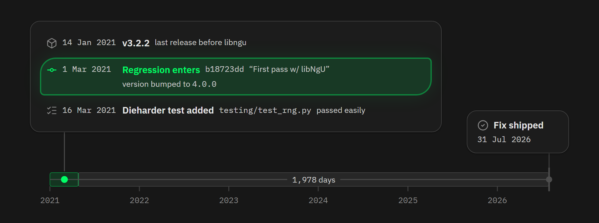
ngu.random.bytes is implemented in C inside libngu, Coinkite’s in-house cryptographic library. Coldcards have not always relied on it: up to version 3.2.2, released on 14 January 2021, they used 2 external submodules, crypto and modcryptocurrency, the first pointing at a fork of trezor-crypto. Commit b18723dd of 1 March 2021, “First pass w/ libNgU”, drops both in favour of libngu and bumps the version to 4.0.0.
The defect entered the code on 1 March 2021, 1,978 days before the fix of 31 July 2026. It reached users 16 days later, with version 4.0.0 of 17 March 2021, which leaves 1,962 days between the first vulnerable release and the fix.
Here is the heart of the function:
void my_random_bytes(uint8_t *dest, uint32_t count)
{
    uint32_t last = 0;
    while(count) {
        uint32_t chip = CHIP_TRNG_32();
        if(chip == last) {
            // maybe TRNG is not clocked? Fail hard
            mp_raise_OSError(MP_EFAULT);
        }
        last = chip;
        chip ^= my_yasmarang();
        ...
    }
}
ngu/random.c:68 - switck/libngu @ 537519a8
Each pass through the loop chains 4 operations:
- read 32 bits from the hardware generator through
CHIP_TRNG_32(), - compare that value with the previous pass,
lastholding 0 on the first one, and raise an error if the 2 are identical, - XOR the result with 32 bits drawn from
my_yasmarang(), - copy up to 4 bytes into the output buffer.
Mixing a hardware source with a software generator through XOR is standard hardening practice. And since the loop advances 4 bytes at a time, building the 32 bytes of a seed takes exactly 8 passes, so 8 calls to each of the 2 generators.
Keep an eye on that my_yasmarang(), because it comes back later. It is a pseudo-random generator whose starting state is hard-coded in libngu: pad = 0x0a8ce26f, n = 69, d = 233 and dat = 0. The same algorithm exists a second time inside MicroPython, with its own starting state, and a 3rd copy sleeps in MicroPython’s urandom module, which never runs, as we will see in section 7.
Which brings us to what CHIP_TRNG_32() actually does.
#ifdef MICROPY_PY_STM
    // ports/stm32/rng.c
    extern uint32_t rng_get(void);
    #define CHIP_TRNG_SETUP()
    #define CHIP_TRNG_32()      rng_get()

    #ifndef MICROPY_HW_ENABLE_RNG
    #  error "get a HW TRNG plz"
    #endif
#endif
ngu/random.c:22-30 - switck/libngu @ 537519a8
This block does 2 things. The first is the #ifndef guard, which I will come back to. The second is the line extern uint32_t rng_get(void);, which tells the compiler that a function called rng_get exists somewhere, without saying where or what it does, and the macro just below wires CHIP_TRNG_32() to it.
So libngu compiles without ever knowing where its randomness will come from. The linker settles it when the firmware is assembled, by looking for a global symbol named rng_get among all the object files. Put another way, libngu orders randomness without saying from whom, and leaves it to the build to fill the blank with whichever supplier happens to carry the right name.
1.1 - The root cause
The Coldcard does have its own board-specific rng.c, and that file really does read the hardware register. Before the fix, though, it exported no global rng_get symbol: its read function, rng_get_or_fault(), was declared static, and so invisible from other translation units. The STM32 port’s Makefile compiles both rng.c files, and only one of the 2 units defined a global rng_get: MicroPython’s.
But the linker did not pick between 2 candidates here, there was only one. Had Coinkite exported its rng_get, there would have been 2 global definitions of the same symbol, and the build would have failed with a duplicate symbol error. The failure comes precisely from the absence of that conflict.
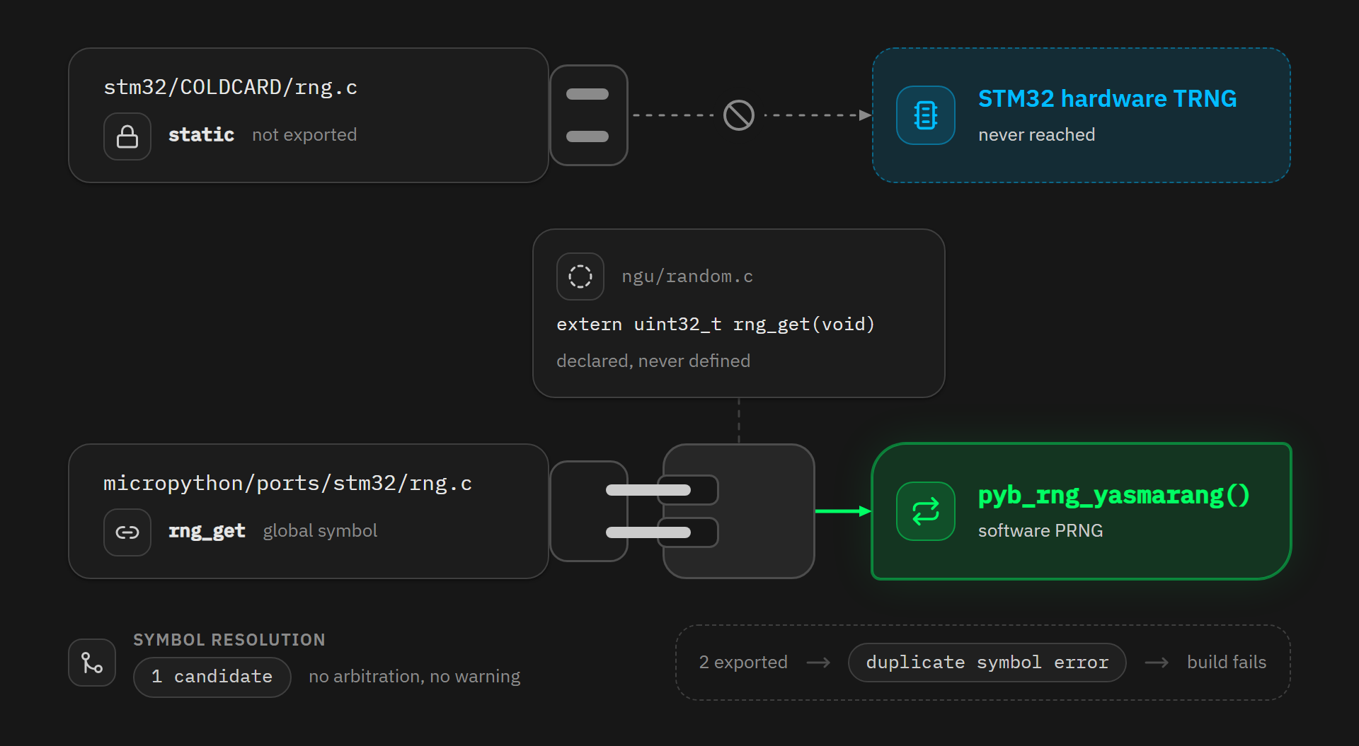
And here is that definition, in micropython/ports/stm32/rng.c:
#else // MICROPY_HW_ENABLE_RNG

// For MCUs that don't have an RNG we still need to provide a rng_get() function,
// eg for lwIP and random.seed().  A pseudo-RNG is not really ideal but we go with
// it for now, seeding with numbers which will be somewhat different each time.

// Yasmarang random number generator by Ilya Levin
// http://www.literatecode.com/yasmarang
STATIC uint32_t pyb_rng_yasmarang(void) { ... }

uint32_t rng_get(void) {
    return pyb_rng_yasmarang();
}
ports/stm32/rng.c:64-99 - Coldcard/micropython @ 4107246f
This fallback exists for microcontrollers with no hardware generator. The Coldcard’s STM32 has one, in all likelihood perfectly functional, and it simply inherited a crutch designed for hardware it is not.
So the operation meant to mix physical noise with a software generator was mixing 2 software generators. And XOR creates no extra entropy, because it is reversible: knowing the result and either input gives you the other, and the entropy of the output is bounded by that of the inputs combined, H(A ⊕ B) ≤ H(A) + H(B). XOR can redistribute randomness, it cannot manufacture it, and when both inputs are sequences computable from a fixed starting state, that sum is zero.
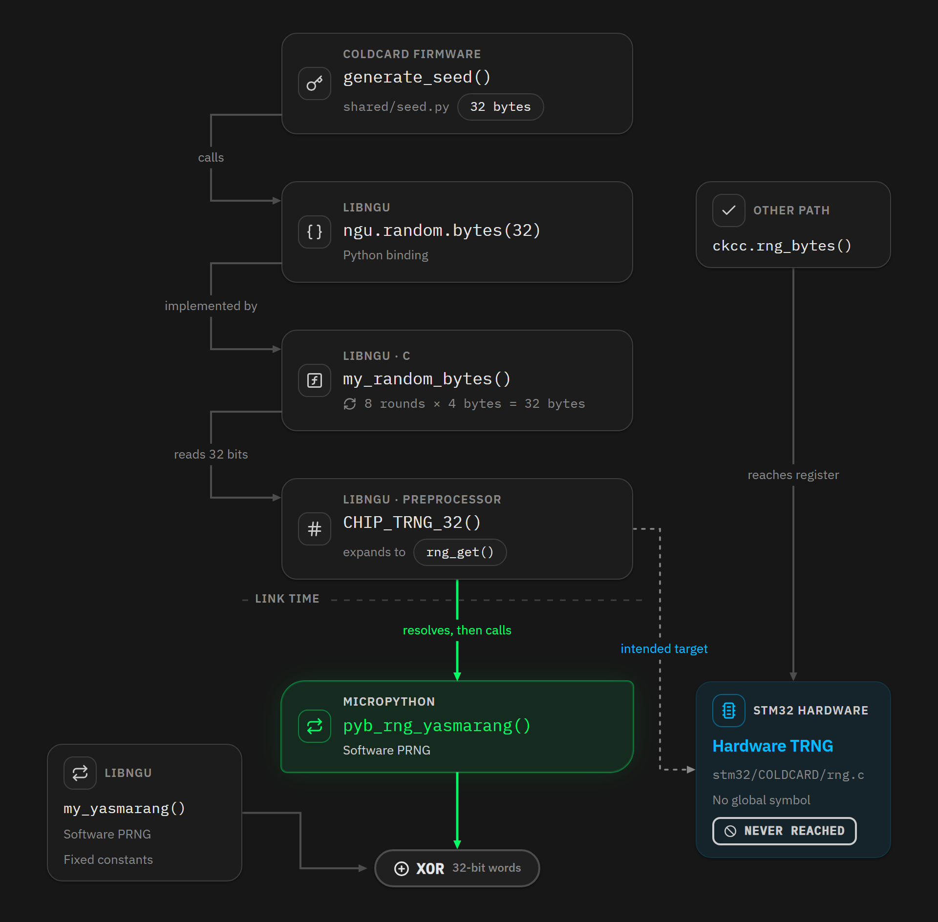
The component itself was not faulty. Other firmware functions were querying it correctly, through a second path going via ckcc.rng_bytes(). It is the ngu.random route, the seed’s route, that was diverted. For 5 years it mixed 2 deterministic computations while believing it was mixing physical randomness with a deterministic computation.
1.2 - The guard that guarded the wrong side
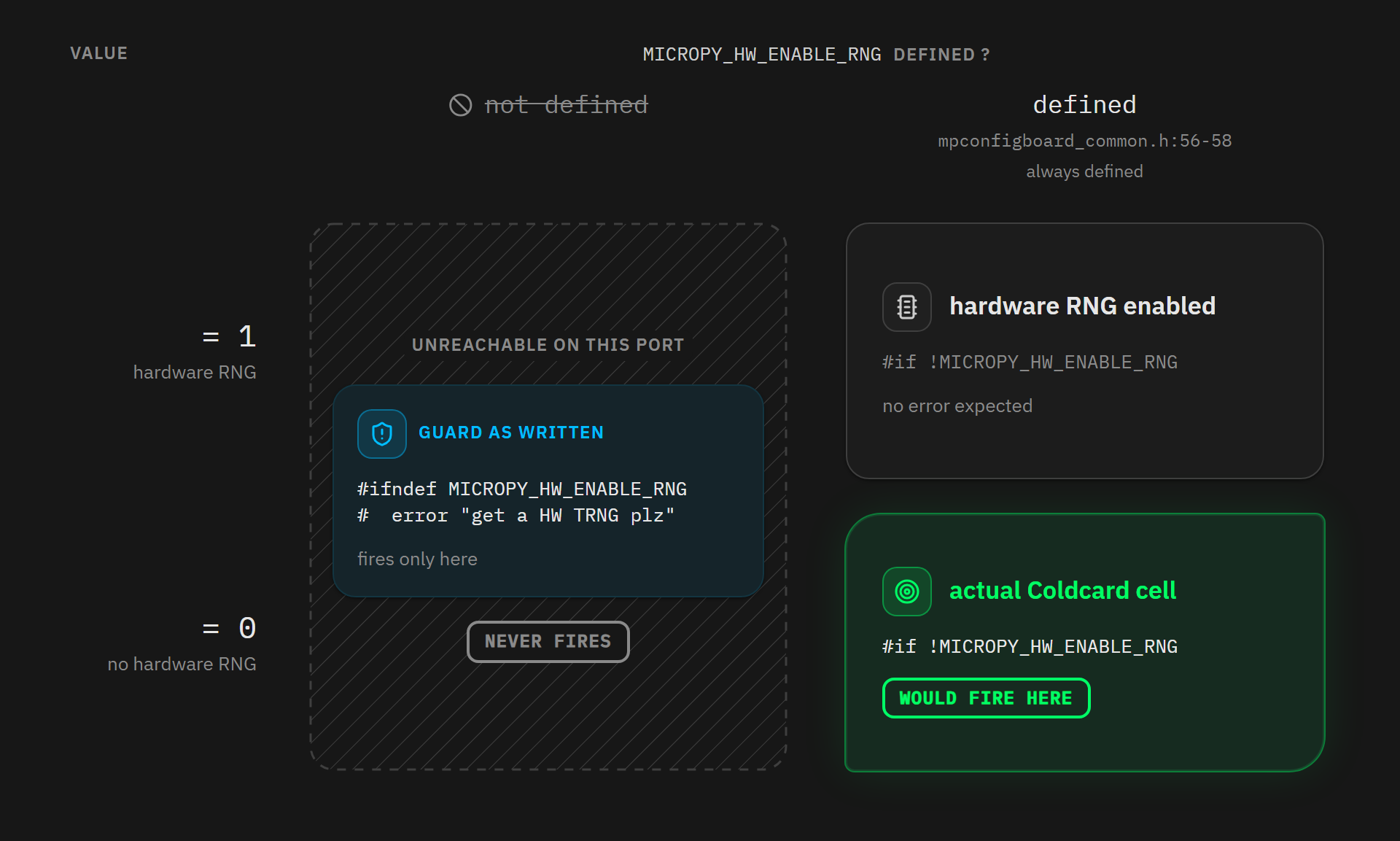
The guard quoted above was meant to prevent exactly this scenario, and our first analysis showed why the #ifndef was not testing what it thought it was testing. What we had not said is that the problem was worse than an oversight:
#ifndef MICROPY_HW_ENABLE_RNG
#  error "get a HW TRNG plz"
#endif
ngu/random.c:28-30 - switck/libngu @ 537519a8
On the STM32 port, mpconfigboard_common.h:56-58 always defines that symbol, defaulting to 0:
// Whether to enable the hardware RNG peripheral, exposed as pyb.rng()
#ifndef MICROPY_HW_ENABLE_RNG
#define MICROPY_HW_ENABLE_RNG (0)
#endif
ports/stm32/mpconfigboard_common.h:56-58 - Coldcard/micropython @ 4107246f
That guard was therefore structurally unable to fire on this platform, whatever the project configuration.
Testing the value instead of the definition does not fix it either. #if !MICROPY_HW_ENABLE_RNG fires the error on every Coldcard build, because the macro is 0 on purpose :
// We have our own version of this code.
// LATER: when zero, this selected some PRNG code we really didnt want.
#define MICROPY_HW_ENABLE_RNG       (0)
stm32/COLDCARD_MK4/mpconfigboard.h:77-79 - Coldcard/firmware @ master
And the board’s own rng.c enforces that choice in the same tree, in the very file whose symbol was not exported:
#if MICROPY_HW_ENABLE_RNG
#error "this code replaces normal RNG module"
#endif
stm32/COLDCARD/rng.c:40-42 - Coldcard/firmware @ bcc2c382
Set the macro to 0 and libngu’s test rejects the build. Set it to 1 and this second guard rejects it, because the board file only compiles when it replaces the platform module. No value passes both. Coinkite merged that exact change into libngu on 6 August 2026, from #ifndef to #if MICROPY_HW_ENABLE_RNG == 0, and reverted it the next day. The revert message states that it breaks all Coldcard firmware builds.
The guard that actually works therefore tests 2 conditions instead of one: #if MICROPY_HW_ENABLE_RNG != 1 && NGU_STM32_EXTERNAL_RNG_GET != 1. The second macro is the board’s explicit opt-in, the signal that an external, hardware-backed rng_get is on the way. This is the form libngu’s main branch carries today, at ngu/random_backend.h:27.
2 - Yasmarang, the generator that took the TRNG’s place
Since everything rested on this generator, it is worth a closer look.
One clarification first, because the firmware ships 2 copies of it. The one that matters here is MicroPython’s: that is the one that took the TRNG’s place, and the one the unique identifier seeds. libngu’s, met earlier, is a separate copy of the same algorithm with its own constants. In the shipped firmware, then, the same algorithm runs in 2 places at once, in 2 libraries that know nothing of each other, and their 2 outputs end up mixed by the XOR.
libngu’s copy, my_yasmarang(), has its starting state hard-coded. On the Mk2 and Mk3 it produces the same byte sequence on every device on the planet. On the Mk4, Mk5 and Q a reseed at boot modifies it, which is, in all likelihood, what saved the funds of those models’ owners.
MicroPython’s copy, pyb_rng_yasmarang(), is the one the linker wired behind rng_get(): it is the one that answers when libngu believes it is querying the hardware generator, and its starting state changes from one device to the next, since its seeding reads the chip’s unique identifier and the SysTick.
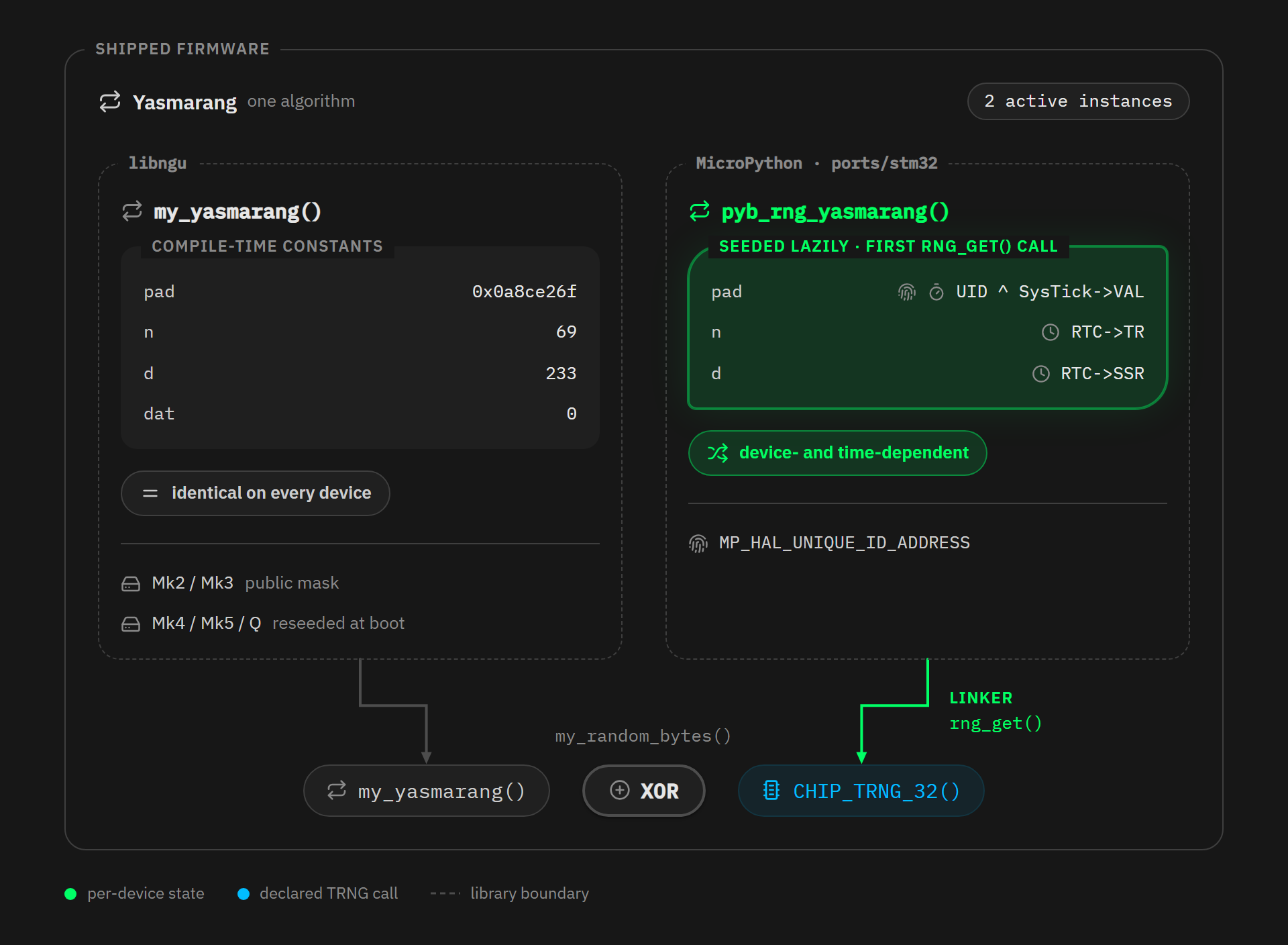
On the Mk2 and Mk3, then, the seed depends on nothing but this second copy, the first only adding a mask that is identical on every device at a given draw rank, and that anyone can recompute, since its input is hard-coded.
Everything that tells your Coldcard apart from your neighbour’s is locked inside the starting state of the function below.
STATIC uint32_t pyb_rng_yasmarang(void) {
    static bool seeded = false;
    static uint32_t pad = 0, n = 0, d = 0;
    static uint8_t dat = 0;

    if (!seeded) {
        seeded = true;
        rtc_init_finalise();
        pad = *(uint32_t *)MP_HAL_UNIQUE_ID_ADDRESS ^ SysTick->VAL;
        n = RTC->TR;
        d = RTC->SSR;
    }

    pad += dat + d * n;
    pad = (pad << 3) + (pad >> 29);
    n = pad | 2;
    d ^= (pad << 31) + (pad >> 1);
    dat ^= (char)pad ^ (d >> 8) ^ 1;

    return pad ^ (d << 5) ^ (pad >> 18) ^ (dat << 1);
}
ports/stm32/rng.c:74-94 - Coldcard/micropython @ 4107246f
Yasmarang is a generator written by Ilya Levin. It is designed for uses where statistical quality is enough, it never claimed to be cryptographic, and it is not: its output function is a linear combination of its state through shifts and XORs, with no one-way function anywhere.
How much can that state hold? pad is 32 bits, n 32 bits, d 32 bits and dat 8 bits, which makes 104 raw bits. Look at the 3rd line of the function body, though: n = pad | 2. On every pass, n is entirely recomputed from pad, so it is not an independent state variable but a derived value, and from the very first iteration it stops carrying any information of its own. The effective state comes down to pad + d + dat, which makes 72 bits.
3 - The chip’s unique identifier
3 sources seed this generator, once only, on the very first call. Let us take them one at a time, starting with the one that gives this section its title.
pad = *(uint32_t *)MP_HAL_UNIQUE_ID_ADDRESS ^ SysTick->VAL;
ports/stm32/rng.c:82 - Coldcard/micropython @ 4107246f
3.1 - One word out of 3, and it is the worst one
Every STM32 carries a 96-bit unique identifier burned in at the factory. On the STM32L4 and L4+ fitted in every Coldcard, it sits at address 0x1FFF7590, defined in mpconfigboard_common.h:239.
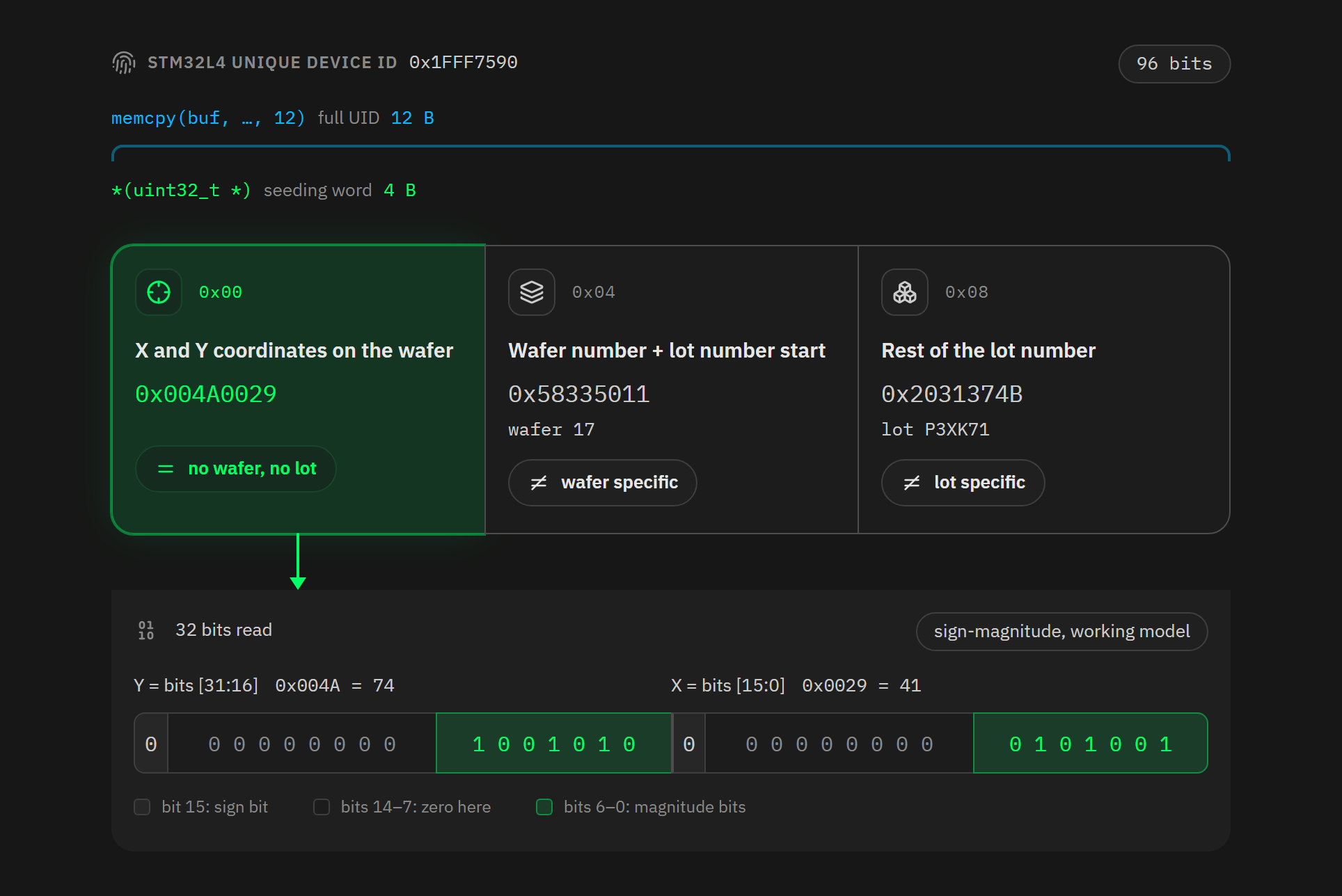
The code does not read the 96 bits. It writes *(uint32_t *), so a single 32-bit word, the one at offset 0. Elsewhere in the same source tree, when MicroPython really wants the full identifier, it writes memcpy(buf, (uint8_t*)MP_HAL_UNIQUE_ID_ADDRESS, 12), in mboot/main.c:736 for instance.
Those 96 bits are not homogeneous, however. ST’s reference manual breaks them down like this:
| Offset | Contents |
|---|---|
0x00 |
X and Y coordinates of the chip on the silicon wafer |
0x04 |
Wafer number, plus the start of the lot number in ASCII |
0x08 |
Rest of the lot number, in ASCII |
The word the generator reads is the one at offset 0x00, the only one of the 3 that tells neither one wafer from another nor one lot from another. Uniqueness comes from the 3 words together: the 2 the code ignores identify the lot and the wafer, and the word it reads identifies the die inside that wafer. Reading that word alone collapses the whole of production onto the positions of a single wafer.
On what that word contains, RM0351, the manual covering the Mk3’s chip, gives one line:
X and Y coordinates on the wafer
ST’s manual for the STM32F0, RM0091, adds “expressed in BCD format”. Neither version says which bits carry X and which carry Y. An ST employee gives the split on the manufacturer’s official forum:
X = bits [15:0] and Y = bits [31:16]
Source: an answer from technical moderator “mƎALLEm” in July 2025, in the thread Parsing UID Fields on STM32L476.
Now we need a real identifier, because what we are trying to measure are the regularities of real silicon, and nobody publishes a survey of STM32 identifiers. That same thread supplies one, posted by a developer decoding his chip, an STM32L476 covered by the same reference manual and the same identifier format as the Coldcards':
0x004A0029 / 0x58335011 / 0x2031374B
It decodes to X = 41, Y = 74, wafer 17, lot P3XK71, and it will be our running example to the end of this section. But this is a very small sample. I add 2 more a little further down, but that will still not make it a statistically meaningful sample.
The BCD wording fails on this sample: 0x4A holds a nibble of 10, which BCD does not allow. ST addressed it in a thread about the STM32C0, moderator “STOne-32” announces a correction to the manual:
X and Y coordinates are coded on 16 bits, most significant bit being the sign bit. So this means that the bit 15 is the sign bit and the 15 others are the coordinate number in hex format.
This is sign-magnitude coding, not two’s complement, so the unused bits do not copy the sign, they stay at zero.
Applied to our first word, 0x004A0029, half-word by half-word:
| Half-word | Bit 15, the sign | Bits 14 to 7 | Bits 6 to 0, the magnitude | Value |
|---|---|---|---|---|
X = 0x0029 |
0 | all 0 | 0101001 |
+41 |
Y = 0x004A |
0 | all 0 | 1001010 |
+74 |
The 8 middle bits are empty on the chips we care about: with the die sizes seen below on a 300 mm wafer, the grid never exceeds 70 columns or 80 rows, so 7 magnitude bits are enough. On smaller chips the grid is wider and those bits do get used.
The sign bit, meanwhile, is 0 on both our coordinates, and 2 outside data points point the same way. The developer in the STM32C0 thread, who handles these chips all year round, observes that the sign-carrying bytes are “always 0” across everything he has seen. And dicing map formats count cells from a corner of the wafer, the lower-left corner being the default in the SEMI E142 standard. A negative coordinate on an STM32L4 would prove me wrong, but I have not found one.
2 more real identifiers point the same way. An issue in the Zephyr project, opened because the USB serial number of STM32 devices is not unique, publishes the full identifier of 2 STM32L433 chips: 20323742324B500A003B0023 and 20323742324B500A003C0027. They decode to X = 35, Y = 59 and X = 39, Y = 60, both on wafer 10 of lot PK2B72. Sign bit at 0, leading bytes at 0, magnitudes well under 128: every reading I have found points to the same format. And since these 2 chips come off the same wafer, they occupy 2 different positions, which illustrates in advance a caveat from section 6.2.
The count per coordinate comes to: 7 magnitude bits that carry information, 1 sign bit that carries none, and 8 leading bits at zero. Of the 32 bits on offer, then, at most 14 carry information.
ST raises 2 caveats of its own in that thread:
- The coding “may be impacted by our Different diffusion factories, so either in BCD or Integer, HEX”: in BCD, a coordinate would take 8 bits instead of 7, which moves the useful bits around without changing how many there are.
- The wafer “may be an 8 inch or 12 inch diameter”: a 200 mm disc holds 2.3 times fewer positions, so more collisions.
Add to that the fact that the X/Y split is confirmed only for the STM32L476, and the sign-magnitude format only for the STM32C0. Which of the 2 half-words carries X is therefore guaranteed on no other part number, and in 5.2 I put a number on what swapping them would cost.
In practice, none of these caveats pushes the count outside the 10 to 13 bit range computed later in the article. The diameter one points to a smaller space than the one I use, and so to more frequent collisions, and the coding one is neutral. The only one pulling the other way is the variation in convention between factories: 2 different numbering schemes produce more values in total than a single wafer does. Finally, the only guarantee ST makes, “the coding is unique for the 96-bits”, is about the 96 bits and not about the first 32, which is exactly what this article is about.
A quick word on terminology before we go on, so nobody gets lost. The wafer is the silicon disc on which hundreds of chips are made in one piece, and the die is an individual chip once the disc has been cut. The scribe line is the strip the blade consumes between 2 neighbouring dies, lost but counted in the grid pitch.
3.2 - How many bits is that word really worth?
How many different chips can be cut from a wafer, and therefore how many distinct (X, Y) pairs exist? Counting those positions comes down to laying a grid over a disc and counting the cells fully inside it, which takes 3 numbers: the size of a die, the diameter of the disc, and the width of the scribe line.
First number, the die size. The firmware’s mpconfigboard.mk files give a build target, STM32L475xx for the Mk2 and Mk3 and STM32L4S5xx for recent models, but a build target is not a part number. Coinkite publishes the real ones in the hardware/ folder of its own repository, as manufacturing bills of materials:
| Model | Part at reference U1 in the BOM | Package |
|---|---|---|
Mk3 (bom-mark3b.xlsx) |
STM32L496RGT6 | LQFP64 |
Mk4 (bom-mark4b.xlsx) |
STM32L4S5VIT6 | LQFP100 |
Mk5 (bom-mark5f.xlsx) |
STM32L4S5VIT6 | LQFP100 |
Q (bom-q1d.xlsx) |
STM32L4S5VIT6 | LQFP100 |
So the Mk3 is fitted not with an STM32L475 but with an STM32L496. Coinkite publishes no BOM for the Mk2, about which I can say nothing.
Both parts come in LQFP packages, and an LQFP drawing measures moulded plastic, not silicon. The die size has to come from somewhere else. ST sells the same silicon in several packages, and one of them has no shell at all. In a WLCSP the balls sit straight on the die, so the outline printed in the datasheet is the outline of the chip itself.
So we can look each part up in its WLCSP variant and read the mechanical drawing. DS12024 gives a WLCSP144 for the STM32L4S5xx and DS11585 gives a WLCSP100 for the STM32L496.
| Models | Chip mounted | The same chip, in WLCSP | Dimensions published by ST | Die area |
|---|---|---|---|---|
| Mk3 | STM32L496 | WLCSP100 | 4.618 × 4.142 mm | 19.13 mm² |
| Mk4, Mk5 and Q | STM32L4S5 | WLCSP144 | 5.24 × 5.24 mm | 27.46 mm² |
The first number can be cross-checked. The STM32L496 datasheet, DS11585, publishes 2 WLCSP packages, a 100-ball and a 115-ball, measuring 4.618 × 4.142 and 4.63 × 4.15 mm. 2 different pin counts, 0.3% apart: the pin count does not change the die, and the Mk3’s STM32L496RGT6, in its 64-pin package, shares it. ST also publishes die sizes in plain text in the reliability reports attached to its process change notifications, with 3,176.4 × 3,162.4 µm for die 435, the STM32L431’s, or 10.0 mm². The dies in this family do sit between ten and thirty square millimetres.
The next 2 numbers come from ST’s production documents, but from 2 separate documents. The process change notifications place STM32L4 diffusion at TSMC, in the Fab 14 plant in Tainan, Taiwan, with the Crolles 300 site as a second source: notification MDG/19/10333 states in plain words that “Fab 14 TSMC is a fab already diffusing 90nm used for STM32L4 products”. The 12-inch wafer diameter and the 80 µm scribe line, on the other hand, come from reliability report MDG-MCD-RER1810, which is an assembly qualification report attached to other notifications: the ones adding subcontractor ASE Kaohsiung for the LQFP packages.
Note how far these documents actually go: they cover STM32L4 parts and test vehicles, not the Coldcards’ STM32L496 and L4S5 by name, and the report itself lists several diameters and several scribe lines depending on the die. These are values representative of the family, not certified dimensions for our 2 chips.
Last comes the counting convention, so this can be reproduced. We lay down the grid, whose pitch is the die dimension plus the scribe line, we take off a 3 mm edge margin (my choice, not an ST figure) and we keep only the dies entirely inside the disc once reduced. Where the grid sits on the disc is not documented either, and shifting it by a fraction of a pitch makes the count swing between 3,281 and 3,306 for the Mk3, or 0.011 bit: that is why the tables below round.
| Models | Positions per wafer | In bits |
|---|---|---|
| Mk3 | about 3,300 | 11.7 |
| Mk4, Mk5 and Q | about 2,300 | 11.2 |
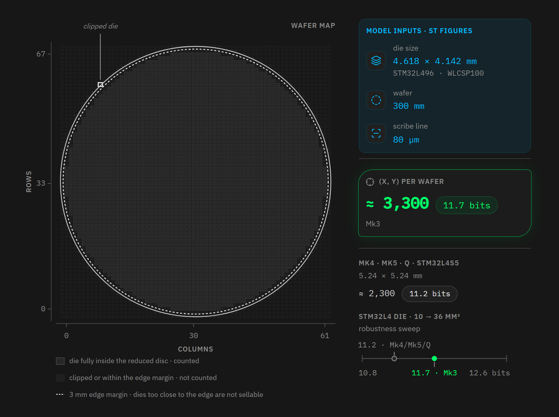
The 0 to 61 columns and 0 to 67 rows are grid indices under my counting convention, not the raw values the identifier word takes. ST documents no coordinate origin, and the few real readings I found (X from 35 to 41 and Y from 59 to 74) suggest the factory numbering starts above zero. A shift of origin changes none of these counts because sliding the labels along an axis renames every cell, but the number of cells inside the disc stays the same.
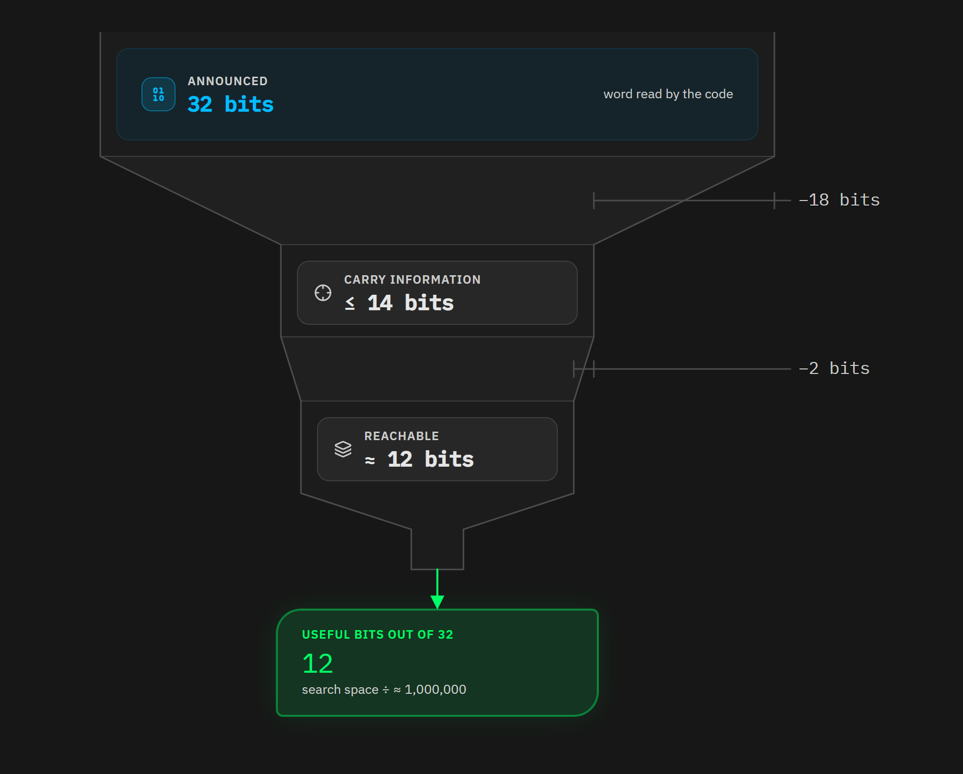
The funnel has 3 stages. First, the 32 bits on offer, the size of the word the code reads. Then at most 14 bits carrying information, once you remove the unused sign bit and the magnitude bits the wafer size never reaches. And finally about a dozen genuinely reachable, because a wafer is round and the grid has only a finite number of cells.
Some twenty bits have therefore evaporated along the way, dividing the search space by a factor close to a million. We also correct our previous article here, which credited these coordinates with about 16 bits: that was an upper bound taken from the orders of magnitude circulating at the time, but the detailed computation brings it down to 12.
3.3 - That word is not a secret
We have just measured the size of this word, but is it secret? Because 12 bits the attacker has to guess and 12 bits he can read are not the same thing at all.
First we need to connect 2 ways of writing the same identifier. So far we have read it as 3 words of 32 bits, whereas Python code receives it through machine.unique_id() as 12 bytes numbered i[0] to i[11].
| Bytes | Contents | On our sample |
|---|---|---|
i[0] and i[1] |
X coordinate | 41 |
i[2] and i[3] |
Y coordinate | 74 |
i[4] |
wafer number | 17 |
i[5] to i[11] |
lot number, in ASCII | P3XK71 |
The first 4 bytes form exactly the word the generator reads. And the Coldcard publishes a serial number over the USB bus, built in shared/version.py:
def serial_number():
    # - this is **probably** public info, since shared freely over USB during enumeration
    import machine
    i = machine.unique_id()
    return "%02X%02X%02X%02X%02X%02X" % (i[11], i[10] + i[2], i[9], i[8] + i[0], i[7], i[6])
shared/version.py:66 - Coldcard/firmware @ bcc2c382
This line publishes i[11], i[9], i[7] and i[6] as they are, all of which belong to the lot number. It publishes 2 sums, i[10] + i[2] and i[8] + i[0], where a lot byte is added to a coordinate byte. And it does not publish i[1], i[3], i[4] and i[5] at all.
A clarification is needed about how reachable this value is, because it is often described as readable by anyone who plugs the device in. That is wrong on a locked Coldcard: in shared/actions.py, the call to enable_usb() happens only after authentication, and it is further gated on the du setting that lets you disable USB for good. Before the PIN, the device does not enumerate at all. The value is still widely exposed: it shows up in the information menu, it travels over the bus as soon as the owner uses the device, and MicroPython computes it with the same formula in its USB descriptor, noting that the STM32’s ROM DFU loader produces the same result. So it is not a secret, but it is not something you read in 3 seconds off a locked device found in a drawer either.
I have seen it written elsewhere that this serial number directly reveals the word the generator uses. That is inaccurate: the 2 coordinate bytes that matter, i[0] and i[2], never appear on their own, they are buried in a sum with a lot byte that the serial number does not give. The practical conclusion holds anyway, by another route. ST documents the lot number as ASCII, which says nothing about the alphabet actually used, since ASCII also contains punctuation, lowercase letters and control characters. But if we assume, based on the readings I have, that this alphabet is limited to the 59 codes running from space to the letter Z, then that byte is worth a few dozen values, not 256.
I redid the computation on the real dump: identifier 0x004A0029 / 0x58335011 / 0x2031374B does produce serial number 207B37745833, and from that number alone, bounding the lot alphabet to the 59 ASCII codes running from space to the letter Z, the coordinate word narrows to 59², so 3,481 candidates and 11.8 bits. Be clear about what that figure is: these are candidates for the coordinate word, not for the pad, which is born of the XOR with the SysTick. This result converges with the geometric estimate obtained independently: about 12 bits from the dicing grid, about 11.8 bits from partially inverting the serial number.
ST documents this alphabet nowhere, but I checked it on a real Coldcard Mk5, reading its serial number off the screen. The 4 lot bytes it publishes in the clear are 3, H, 9 and a trailing space, all within the range assumed, as are the 4 from the forum sample. The 2 STM32L433 chips from the Zephyr issue point the same way: their full lot number, PK2B72, fits in it too. And all 3 readings end in a space, consistent with an ASCII lot number padded on the right.
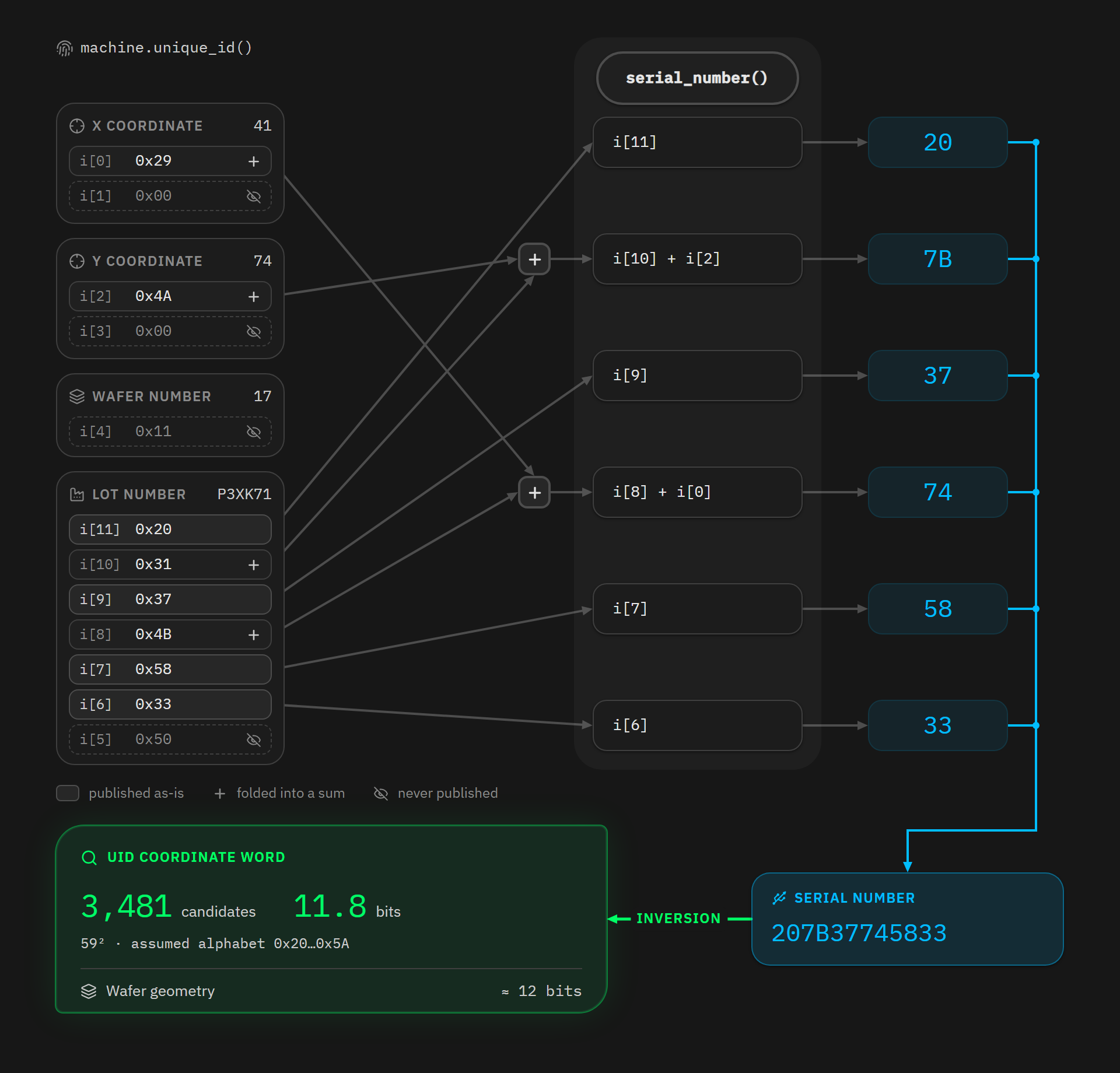
Under this alphabet assumption, an attacker who has plugged in the unlocked device once has 3,481 combinations to try, and one who has never touched it has to sweep the 3,300 positions available on a wafer. Either way, about a dozen bits, which is to say a fraction of a second of computation. This word therefore protects nobody, and the comment the developers themselves left in the code, “this is probably public info”, already said as much.
4 - The 2 thirds of the seed that were worth zero
On to the 2 other seeding sources, RTC->TR and RTC->SSR, the time and sub-second registers of the real-time clock.
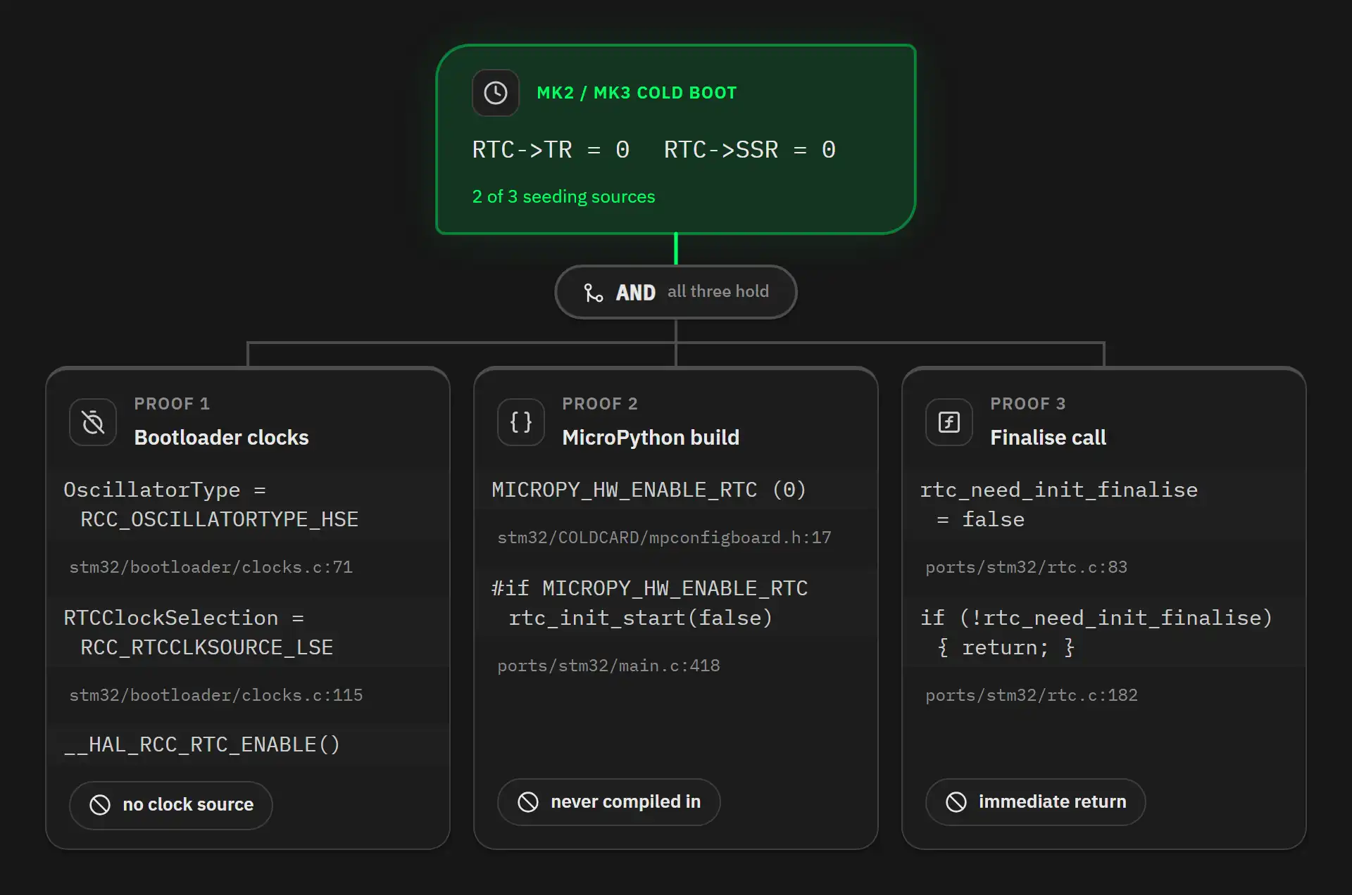
Step one: on the Mk2 and Mk3, the low-speed oscillator that the RTC needs is never started. The bootloader configures exactly one oscillator:
RCC_OscInitStruct.OscillatorType = RCC_OSCILLATORTYPE_HSE;
stm32/bootloader/clocks.c:71 - Coldcard/firmware @ bcc2c382
HAL_RCC_OscConfig guards each oscillator block with a test on that mask:
if(((RCC_OscInitStruct->OscillatorType) & RCC_OSCILLATORTYPE_LSE) == RCC_OSCILLATORTYPE_LSE)
stm32/bootloader/stm32l4xx_hal_rcc.c:601 - Coldcard/firmware @ bcc2c382
The mask holds RCC_OSCILLATORTYPE_HSE alone, so the test is false and the LSE block is skipped entirely. The RCC_LSE_OFF written 3 lines below it never runs. Nothing switches the 32.768 kHz oscillator off, because nothing ever switches it on. On the Mk3 there is nothing to start anyway. Across the 25 line items of the bill of materials there is one single oscillator, Y1, an 8 MHz ceramic resonator. No 32.768 kHz part appears at all.
Back in clocks.c, 44 lines below that mask, the absent oscillator is named as the RTC’s clock source:
PeriphClkInitStruct.RTCClockSelection = RCC_RTCCLKSOURCE_LSE;
stm32/bootloader/clocks.c:115 - Coldcard/firmware @ bcc2c382
RTCSEL selects one source among 3: the LSE, the internal LSI, or the HSE divided by 32. Here it selects the LSE. The LSI is never started, and neither RCC_OSCILLATORTYPE_LSI nor LSIState appears in any clocks.c of the tree. The bootloader calls __HAL_RCC_RTC_ENABLE() 15 lines later, which sets the enable bit in RCC->BDCR and nothing else. The counter has no clock and never increments.
Step two: MicroPython never initialises the RTC on these boards. The 3 mpconfigboard.h files of the Coldcard boards all carry the same line 17:
#define MICROPY_HW_ENABLE_RTC (0)
stm32/COLDCARD/mpconfigboard.h:17 - Coldcard/firmware @ bcc2c382
And in ports/stm32/main.c:418-420, initialisation is gated on that flag:
#if MICROPY_HW_ENABLE_RTC
rtc_init_start(false);
#endif
ports/stm32/main.c:418-420 - Coldcard/micropython @ 4107246f
Step three: the call to rtc_init_finalise() visible in the seeding block does nothing at all. Its first statement is an early return on a flag that is never raised, since it is only set on the rtc_init_start() path we have just seen disabled:
STATIC bool rtc_need_init_finalise = false;   // rtc.c:83

void rtc_init_finalise() {                    // rtc.c:182
    if (!rtc_need_init_finalise) {
        return;
    }
    ...
}
ports/stm32/rtc.c:83 and 182 - Coldcard/micropython @ 4107246f
On the Mk4, Mk5 and Q, the bootloader picks a clock that is very much alive:
PeriphClkInitStruct.RTCClockSelection = RCC_RTCCLKSOURCE_HSE_DIV32; // but unused
stm32/mk4-bootloader/clocks.c:171 - Coldcard/firmware @ bcc2c382
On these models, then, the RTC really is clocked. One objection remains: its registers would still be unreadable, because their bus clock, RTCAPB, is never switched on anywhere in the shipped code. The __HAL_RCC_RTCAPB_CLK_ENABLE() macro does exist in upstream MicroPython, but it is absent from commit 4107246f, the one the firmware pins. The answer depends on the chip fitted, not on the build target.
On the STM32L475xx target, that bit does not exist; ST’s stm32l475xx.h header defines it nowhere. But the Mk3 is fitted with an STM32L496, where it does exist, and RM0351 section 6.4.19 gives RCC_APB1ENR1 a reset value of 0x0000 0400 on the STM32L496xx and L4A6xx, against 0x0000 0000 on the L475xx, L476xx and L486xx. RM0432 gives the same value in the same section for the STM32L4S5 in the Mk4, Mk5 and Q. On the chips actually fitted, that bit is 1 from power-on, and the RTC registers are readable without any code lifting a finger.
Put another way, on the Mk4, Mk5 and Q, RTC->TR and RTC->SSR do return something alive. That something is simply not what the published budgets describe: the counter restarts from zero on every power-up, so it measures not a time of day but the time elapsed since the device was switched on.
On the Mk2 and Mk3, by contrast, the three-step demonstration is complete. The selected source is never started, the counter never increments, and the ghost calendar registers keep their reset value, which is zero. The generator’s full state on these 2 models becomes:
pad = UID[31:0] ^ SysTick->VAL
n   = 0
d   = 0
dat = 0
2 of the 3 advertised entropy sources are worth zero, and the 4th variable, dat, never appeared in the seeding block at all. On the Mk2 and Mk3, this generator’s entire initial state therefore fits in a single 32-bit word.
Take the function body again with n = d = dat = 0: the first line, pad += dat + d * n, becomes pad += 0 and leaves pad untouched, and the 3 following lines recompute n, d and dat from pad alone. From the very first iteration, the whole internal state, and therefore the whole stream produced until power-off, is a deterministic function of a single 32-bit value.
These variables are static, so they live for the duration of one run and go back to zero on the next reboot. Every power-up draws a new pad. This is not a stream frozen for the life of the device, then, it is a stream frozen for the length of one power-up.
5 - Where do the 40.7 and 73.3 bits come from?
2 figures have been circulating since the attack: a space of 2^40.7 for the Mk2 and Mk3, and 2^73.3 for the Mk4, Mk5 and Q. They come from Block’s analysis, which gives them as strict upper bounds, the second one on condition that the reseed worked.
They can be reconstructed, which shows exactly what they count: they add up the 3 seeding sources we have just walked through. The 80,000 possible SysTick values are worth 16.29 bits, the 86,400 seconds in a day of RTC->TR another 16.40, and the 256 positions of RTC->SSR 8 more, so 40.69 in total. On recent models that count raises the SysTick to 120,000 values and adds the 32 bits of the secure-element reseed, which gives 73.27. Those 120,000 values are themselves wrong, as section 7 shows.
But there are 2 problems here.
5.1 - What the RTC registers are really worth
The 24.4 bits credited to the RTC count a time of day, with its 86,400 seconds and its 256 sub-second positions. Yet none of the 3 repositories ever sets that calendar. On the Mk2 and Mk3, those bits are worth exactly zero, the previous section’s demonstration being complete.
On the Mk4, Mk5 and Q it is different. The bootloader does put the RTC on a clock, on HSE divided by 32. With these boards’ 8 MHz oscillator, that gives 250 kHz, and with the prescalers left at their reset values, RTC->SSR moves one step every 512 microseconds and RTC->TR by one “second” every 131 milliseconds. These 2 registers do not give a time of day, they give the time elapsed since power-on. What they capture is the delay until the first key press, which is when the seeding happens on these models.
That delay is not contained in the SysTick, which only gives the position inside the current millisecond. Sharing an oscillator does not make 2 quantities redundant, it makes them correlated, and that is not the same thing: a source correlated with another can still carry information the other does not. The RTC is therefore not worth the 24.4 bits the count above lends it, but it is not worth zero either.
5.2 - 2 sources in a single word
Next, neither Coinkite nor Block counts a single bit for the unique identifier. Block says so explicitly: its bounds assume the UID is known. It also warns that the 2 values “collapse into one 32-bit pad”, so the total cannot be 2^(32 + SysTick bits). It is tempting to add the identifier’s 11 to 12 bits to the SysTick’s 16.3, which would give 28 bits for an Mk3. That is wrong:
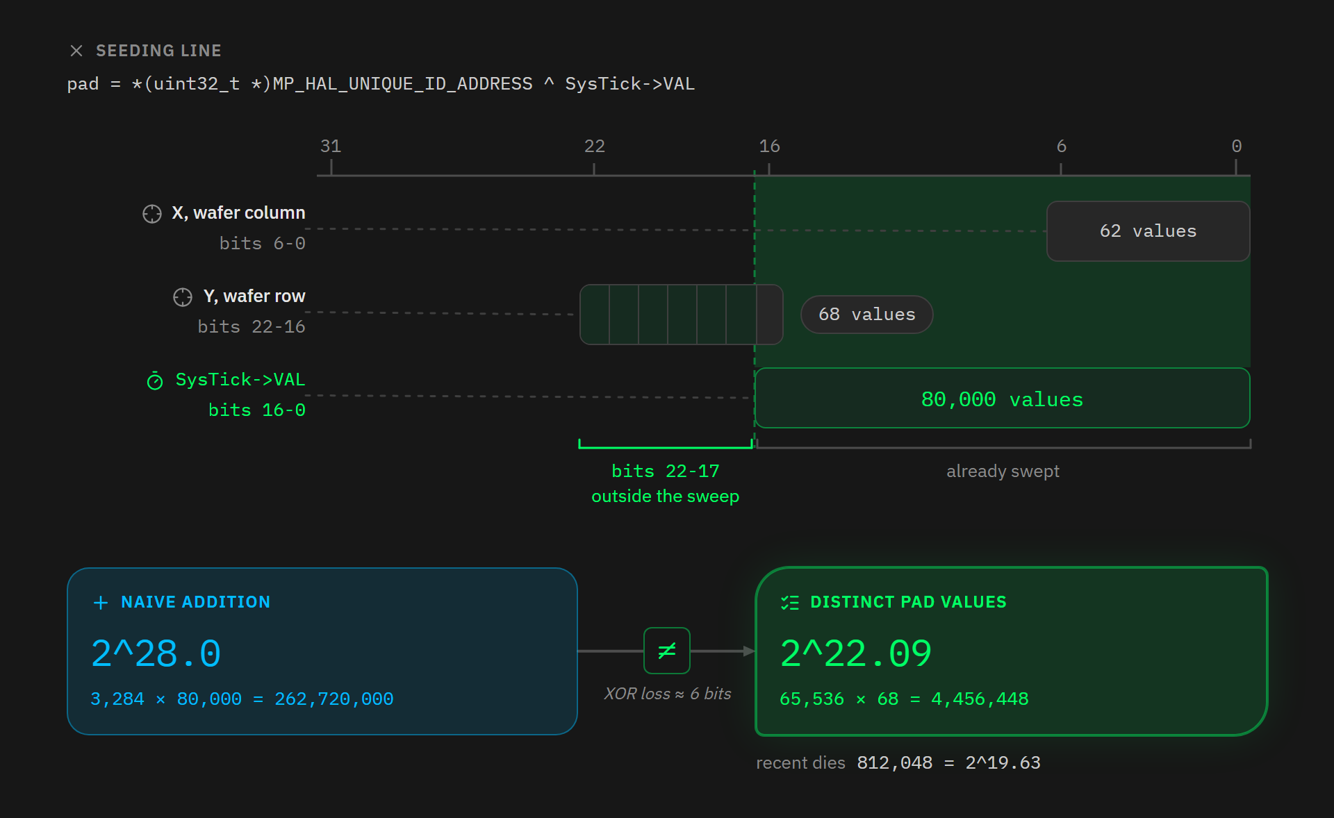
pad = *(uint32_t *)MP_HAL_UNIQUE_ID_ADDRESS ^ SysTick->VAL;
ports/stm32/rng.c:82 - Coldcard/micropython @ 4107246f
The 2 sources do not occupy 2 separate slots, they are XORed into the same 32-bit word. Adding bits up assumes each source has a place of its own, and here they overlap. Here is where each one sits, on an Mk3:
| Field | Bits occupied | Possible values |
|---|---|---|
| X, the column on the wafer | 0 to 6 | 62 |
| Y, the row on the wafer | 16 to 22 | 68 |
SysTick->VAL |
0 to 16 | 80,000 |
The 62 columns and 68 rows are the populated dimensions of the grid built in 3.2, 3 mm edge margin included. ST does not document which of the 2 axes carries X, and swapping them moves the result from 2^22.09 to 2^21.95.
The 80,000 is not a power of 2 because the firmware (not the hardware) sets the counter’s range. It reloads the SysTick every millisecond, which at the Mk3’s 80 MHz comes to 80,000 cycles. See section 7 for more details.
X lives entirely inside the range the SysTick already sweeps, so mixing it in changes which value you get, not how many values are reachable. Y’s low bit, at position 16, also falls in that range. Only bits 17 to 22, that is Y’s 6 high bits, land where the SysTick never goes.
For the Mk3 die’s 3,284 positions and the SysTick’s 80,000 values, we do get 262,720,000 starting pairs, or 2^28.0, but those pairs produce only 4,456,448 distinct pad values, or 2^22.09.
Example: take the real identifier from 3.1, 0x004A0029, and the chip one column over on the same row. The 2 words then differ only in the lowest bit. Seed the first at SysTick->VAL 0 and the second at 1, and the XOR lands on the same value:
| Chip | Identifier | SysTick->VAL |
Resulting pad (XOR) |
|---|---|---|---|
| A | 0x004A0029 |
0x00000000 |
0x004A0029 |
| B | 0x004A0028 |
0x00000001 |
0x004A0029 |
Neither the identifier nor the counter matches, only the result does. Across the whole space, an average of 59 of the 262,720,000 pairs land on each of the 4,456,448 reachable values.
The low 16 bits of pad take all 65,536 of their values, its high half takes only 68, and 65,536 × 68 = 4,456,448. This count assumes the grid indices start at 0, a convention ST does not document: starting them at 1, the set of rows stops being stable under Y xor 1 and the total rises to 4,485,376, or 0.009 bit more. On the recent models’ die, the same shift takes it from 812,048 to 812,112. The order of magnitude does not move, but the exact figure hangs on that convention.
That factor of 59 is worth almost 6 bits, and it is the second time the count drops. The 2 drops have different causes. In 3.2 the bits were gone because the word can never take those values. Here all 4,456,448 values are reachable, and what never existed is the 2^28, since adding the sources counts 2 slots where the code writes into 1. On the recent models’ die, the same count gives 812,048 values, or 2^19.63. The drop is sharper still there, for a reason that owes nothing to geometry: the SysTick only takes 15,000 values on those models, as section 7 demonstrates, so it no longer covers the whole lower half of the word.
Careful, though: these figures are candidate space sizes, not entropy measurements. An attacker has that many states to walk through, but nothing says they are equiprobable, and if the SysTick distribution is peaked, the real entropy is lower still.
5.3 - The corrected table
| Model | Published figure | After correction |
|---|---|---|
| Mk3 | about 40 bits | about 2^22 candidates |
| Mk4, Mk5 and Q | about 72 bits | on the order of 2^52 candidates |
On the Mk3, the generator’s full state reduces to pad alone, which takes 2^22.09 values. On the Mk4, Mk5 and Q, the 2^19.63 values of pad combine with the 32 bits of the secure-element reseed, because these 2 quantities live in 2 different generators, each with its own state word. That gives an order of magnitude of 2^52, and not a floor: the reseed’s 32 bits are themselves a ceiling, as section 8 of this article shows, and the RTC’s contribution, non-zero but unmeasured, pulls the other way. The figure should therefore be read as a scale, not as a minimum guarantee, and it counts neither the RTC nor the draw rank.
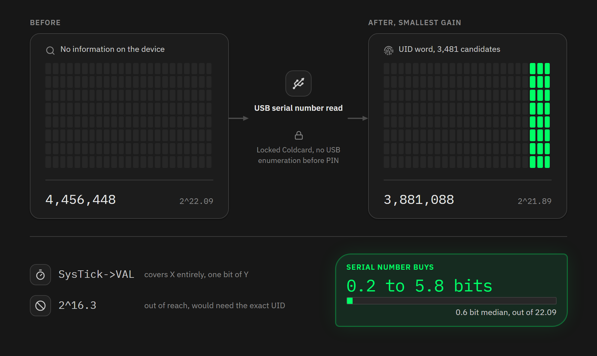
Some published analyses distinguish the case where the attacker has been able to see the device. Across both families, that distinction changes almost nothing. On an Mk3, for instance: the SysTick there already sweeps the whole X coordinate and Y’s low bit, so the serial number can only narrow Y’s 6 high bits. On the forum sample, it brings the coordinate word down to 3,481 candidates and the pad space to 3,881,088 values, or 2^21.89 against 2^22.09: 0.2 bit gained.
That 0.2 bit is a floor, obtained from the serial number alone and under the same alphabet assumption. Cross it with the dicing grid’s 68 rows and the gain depends on the device, because the published sum places the window of possible Y values more or less deep in the grid. That works out at 0.6 bit in the median case and 5.8 bits in the worst one. The gain stays under one bit in 70% of cases with every row weighted equally, and in 75% with each row weighted by the number of dies it holds. On recent models, where the SysTick only sweeps 15,000 values, the same computation gives 0.4 bit at the median.
Dropping to the 16.3 bits of the SysTick alone would require the exact coordinate word, so i[0] and i[2]. Pulling them out of the published sums means resolving the 2 lot bytes those sums hide, i[8] and i[10]. The third hidden lot byte, i[5], enters no sum.
6 - The collision risk between 2 Coldcards
A question has been going round on Twitter these past few days: could this flaw have produced seed collisions across different affected users? Let us try to put numbers on it.
6.1 - 2 devices, one single value
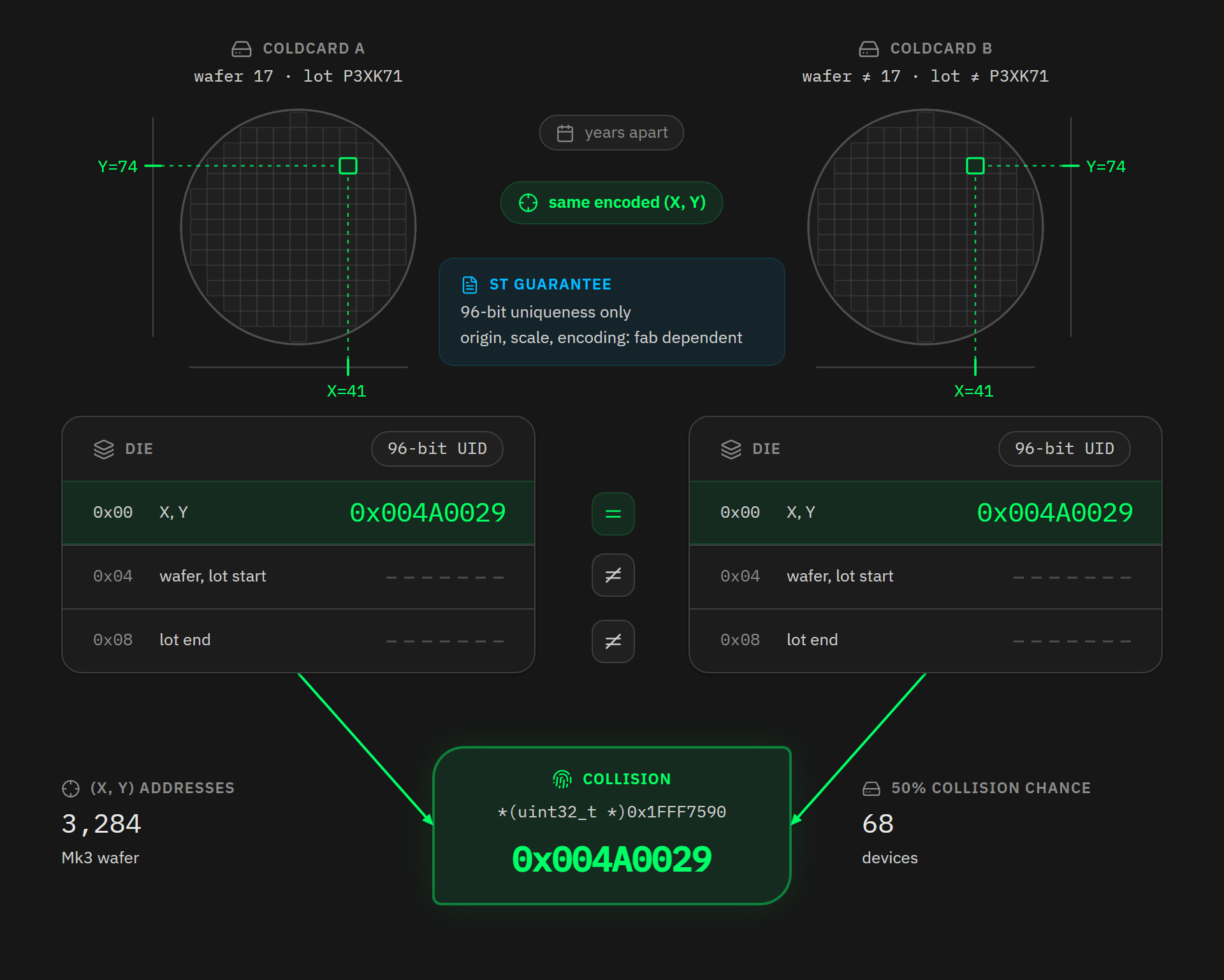
The word being read contains nothing but the chip’s coordinates on the wafer, and everything that tells 2 wafers apart, wafer number and lot number, lives in the 2 words the code does not read. As a result, 2 STM32L4 chips from 2 different wafers, from 2 different lots, made years apart, but carrying the same encoded (X, Y) pair, hold the same value at *(uint32_t *)0x1FFF7590, bit for bit.
The phrase here has to be “the same encoded pair” and not “the same physical position”, because ST nowhere guarantees that the origin, the scale and the encoding convention are identical from one factory, one revision or one process to the next.
6.2 - The birthday paradox
We now know how many different values this word can take: as many as there are positions on the grid, so about 3,300 for an Mk3 and 2,300 for a recent model. Call that number K.
How many devices does it take for 2 of them to land on the same value? This is the birthday problem, the one where a room of 23 people already gives a 1 in 2 chance that 2 of them share a birthday, even though a year has 365 days. The result surprises people because the question is not whether someone shares your birthday, which would take hundreds of people, but whether any pair at all exists in the room, and the number of pairs grows far faster than the number of people.
The 50% threshold is approximated by the following formula, where N is the number of devices and K the number of possible values, and where the factor 1.1774 is the square root of twice the natural logarithm of 2:
N ≈ 1.1774 × √K
Applied to our grid, computing the exact thresholds rather than using this approximation, which underestimates some of them by one:
| Distinct positions K | Entropy | Devices for a 50% collision |
|---|---|---|
| 2,048 | 11.0 bits | 54 |
| 4,096 | 12.0 bits | 76 |
| 8,192 | 13.0 bits | 107 |
So it takes fifty to a hundred Coldcards for there to be a 1 in 2 chance that 2 of them read the same word, and with the 3,284 positions counted for the Mk3 die, the exact threshold works out at 68 devices. Across a fleet of a few tens of thousands of devices, the collision then becomes hard to avoid, with each identifier value shared on average by about ten Coldcards.
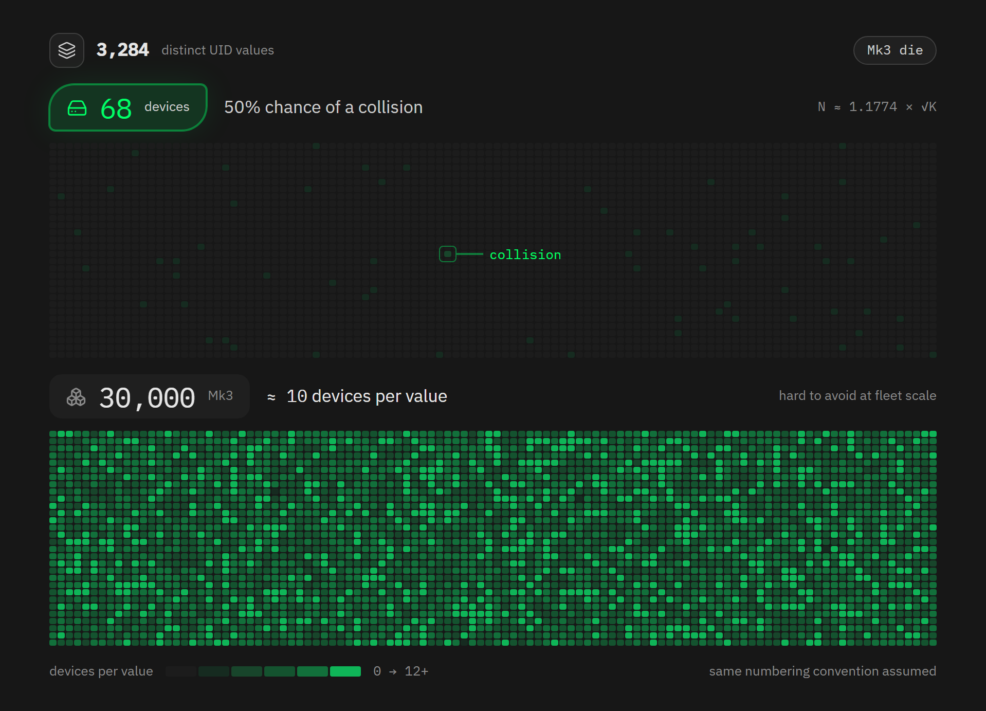
There is a fair objection to this model. The birthday formula assumes independent, uniform draws with replacement, and that is not quite what happens in a factory. 2 effects depart from it, in opposite directions:
- 2 chips cut from the same wafer necessarily occupy 2 different positions, so between them a collision is not unlikely, it is impossible. It only appears between wafers, which pushes the threshold up.
- Manufacturing yield is not uniform across the disc, since edge dies fail testing more often. The surviving chips cluster, and a clustered distribution produces more collisions than a uniform one, which pulls the threshold back down.
The figure of 68 therefore assumes Coldcards sampled in the field, from many wafers and many lots, but sharing the encoding convention, the grid and the wafer diameter used in 3.2. And ST itself says the coding can change from one factory to another and the disc can go from 12 to 8 inches. This threshold holds for a homogeneous sub-population, not for worldwide production, whose number of distinct values remains unknown for lack of samples. And for a batch of devices off a single wafer, it means nothing at all.
That leaves the question of how many devices we are talking about, and this is the weakest link in my whole argument, because no reliable figure exists. Coinkite has never published its volumes, and since the company publishes no GitHub release of its firmware, we cannot even get an estimate that way. 3 routes do converge on an estimate, though:
- By the market: Foundation Devices announced in late 2022 that it had sold “thousands” of Passports, and that device’s firmware now totals 108,000 downloads across 26 versions, nearly 18,000 of them on the latest one alone, which puts a device in this niche in the thousands or tens of thousands of units.
- By the company: a profile published by Bitcoin Magazine in April 2025 describes Coinkite as employing fewer than 20 people, and the GitHub repository backs that up, with 2 developers writing 96% of the 324 commits of the past 12 months.
- By the theft itself: in its 1 August tally, Galaxy Research counted 4,585 addresses and 1,367 bitcoin, a total that has grown since, which probably corresponds to a few hundred to a few thousand distinct seeds.
None of these 3 routes measures the installed base. Each brackets the volume without counting a single device, and together they put the Mk3 somewhere between thousands and tens of thousands. I use 30,000 from here on. It is a working assumption and not a measurement. Everything downstream that scales with the fleet inherits that weakness.
6.3 - 3 levels of collision not to be confused
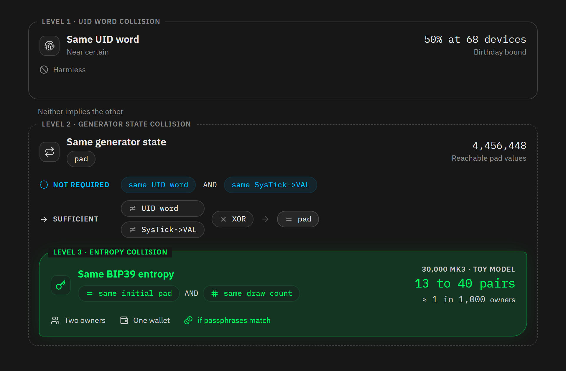
The first level is a collision of the identifier word. It reaches a 1 in 2 chance from 68 devices onwards and becomes near certain in the low hundreds, but on its own it has no consequence.
The second level is a collision of the generator’s full state, that is, of pad alone. Note that it does not require 2 devices to have both the same identifier word and the same SysTick->VAL. Since the 2 are XORed together, it is enough for the result of the mix to be the same, which also happens between 2 devices whose identifier and SysTick both differ. The 2 devices then produce the same byte stream.
The third level is a collision of the BIP39 entropy itself, the entropy that produces the 24 words. Getting all the way to the wallet takes more, though: in shared/stash.py:123, the firmware calls bip39.master_secret(words, _bip39pw), and the passphrase goes into the PBKDF2 salt as BIP39 requires. 2 devices producing the same 24 words share the same wallet only if their passphrases match too, which is the common case since the empty passphrase is the default. When that happens, either owner can spend the other’s funds.
6.4 - The Mk3 case, where the 3 levels meet
On the Mk4, Mk5 and Q, libngu’s generator is reseeded at boot with 32 bits from the secure elements, so a seed collision would require both seedings to coincide at once, which makes it negligible in practice.
On the Mk3 there is no reseed: the mechanism is absent from the v4-legacy branch, where the shared/mk4.py file that carries rng_seeding() simply does not exist, and the second generator starts from its hard-coded constants, identical on every device on the planet.
A collision of the 24 words then takes 2 conditions:
-
that both devices share the same initial
pad, that is, the same XOR result (not necessarily both inputs separately), -
and that they made the same number of draws between that seeding and generation.
The first factor can be computed directly. The 4,456,448 pad values are not equiprobable, and what governs a collision is not how many there are but the probability that 2 devices land on the same one, which is the sum of the squared probabilities. It works out to 1 in 3.7 million, slightly more than the 1 in 4.46 million you would get by assuming uniformity. Across the assumed fleet of 30,000 devices, that makes 450 million pairs to examine, so about 120 pairs of devices producing the same byte stream.
For the second factor, the generator is seeded on the very first draw, which is the first key press, as section 7 details. Each burst then consumes 3 calls to rng_get(), one per draw of the Fisher-Yates shuffle over the keypad’s 4 rows, and libngu’s copy advances at least as much, once more for every rejected draw, at random.c:133. What counts is not how many keys were pressed but how many bursts there were, since a burst only closes 250 milliseconds after the last release. 2 devices sharing the same starting pad but whose owners triggered 10 and 12 bursts are not at the same point in the same sequence, and produce 2 different entropies.
How many values can that count take? Let us set up a toy model, the simplest possible one. The path through a new device is signposted and menu navigation is the same for everyone, so only one choice really varies from user to user: the length of the PIN. In login.py:14-15, that code is made of 2 parts of 2 to 6 digits each, so a total between 4 and 12 digits, entered twice at creation. That makes 9 possible lengths, so 9 classes of user.
This model does not describe the real firmware, and it is worth saying so straight away. _start_scan() is only called at the beginning of a burst, and a burst only closes 250 milliseconds after the last release, at mempad.py:159. 2 people entering a PIN of the same length do not, then, consume the same number of draws: the fast typist chains several keys into a single burst, the hesitant one triggers a burst per key. Add to that backtracking, abandoned attempts, mistyped entries, and the _rand_below() loop that redraws when a draw is rejected. The generator’s real rank at creation time depends on typing cadence, not on PIN length.
Within the toy model, the 2 bounds can be computed: if every user picks the same length, the factor is 1 and takes nothing away, and if they spread evenly across the 9 classes, it drops to 1/9. Still within this model, we can assume the distribution leans towards the top of the range, because people generally pick round lengths, 4+4 or 6+6 rather than 3+5, and if 3 lengths hold most of the fleet, the factor lands around 1/3.
Take the 120 pairs from the first factor again, the ones sharing the same starting pad. The second factor can only eliminate them one by one: the 2 devices that reached generation at the same rank stay in, the others drop out. From that side, 120 is a ceiling. It is not one in absolute terms, because the 120 itself assumes a uniform SysTick: if it is peaked, more devices share the same pad and it is the starting count that rises. With the 1/3 factor, the toy model leaves 40 pairs sharing the same BIP39 entropy across the whole Mk3 fleet, and 13 with a 1/9 factor, still on the assumed basis of 30,000 devices sold.
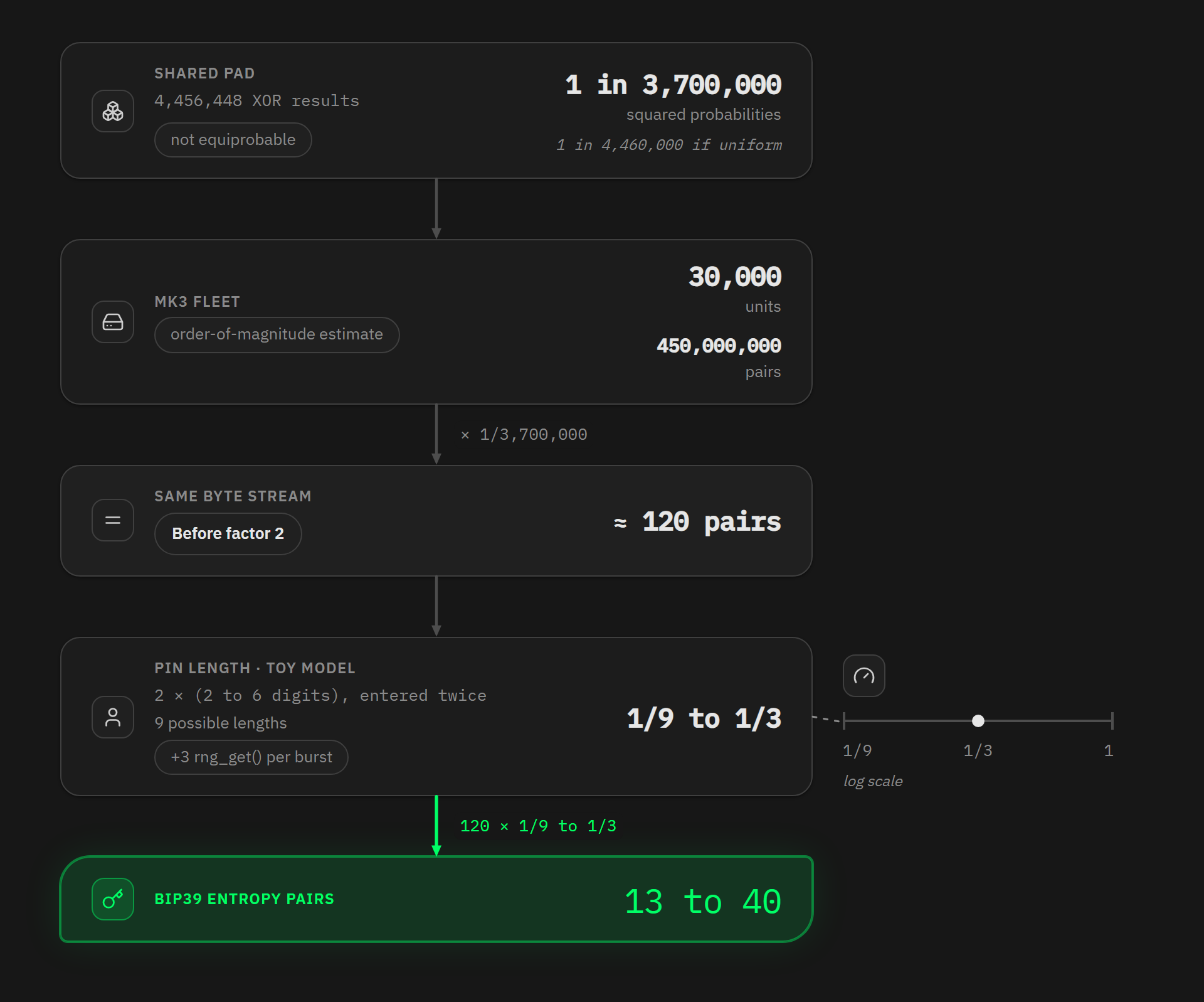
That range of 13 to 40 has to be read for what it is: the output of a toy model, not a measurement. The 9 classes exist only in the model. In the real firmware, the rank depends on bursts, typing cadence, re-entries and rejected draws, so it can form far more than 9 classes, and nothing puts a 1/9 floor under it. What holds without this model is the first factor: about 120 pairs of devices share the same starting pad across the assumed fleet of 30,000, and therefore produce the same byte stream. How many of them reach generation at the same rank, nobody can say without measuring the distribution of real ranks.
This is where the difference between the levels really counts. A collision of the identifier word alone is near certain, and harmless. A collision of the 24 words would touch a few dozen devices in the assumed fleet of 30,000 under the toy model, so on the order of 1 in 1,000, and both owners still have to have left the passphrase empty for them to share a wallet. Rare for any given person, then, but not ruled out.
6.5 - The wafer geometry shows through in the output
Since the generator’s first output is essentially a rotation of pad, 2 devices whose starting pad values are close produce correlated first outputs. Here is the simulation, with 2 values one apart, which corresponds to 2 neighbouring columns on the wafer:
pad = 0x0012000a  ->  099005d6 6806cb91 0757cd65 84f9d609
pad = 0x0012000b  ->  0990054e cc08b5ab 3f8f3f45 614fe347
To measure this we count how many bits differ between 2 outputs, which is the Hamming distance. The reference point is simple: 2 unrelated values share half their bits on average, so 16 out of 32, and the lower you go below that figure, the more alike the 2 outputs are. Sweeping the roughly 3,200 neighbouring pairs on each axis of the Mk3 grid gives this, in bits of difference out of 32:
| Neighbouring dies | 1st output | 2nd output | 3rd output |
|---|---|---|---|
| Same row, next column | 3.7 | 13.9 | 16.1 |
| Same column, next row | 5.7 | 9.0 | 13.8 |
2 details sit under those averages. On the column axis the first output shares 23 high bits, 24 on the pair above. On the row axis, every step from an even row to the odd row after it gives exactly 3 bits of difference and 8 shared high bits, with no exception across the grid.
The correlation is real on both axes and takes a different shape on each. On the column axis it is gone by the third output, at 16.1 bits. On the row axis it is still there, at 13.8. A distance of 16 bits means the Hamming metric detects nothing, not that the 2 streams are independent. What holds, and this is the point that matters, is that the geometry of the dicing grid shows through in the first output.
One special case is worth pausing on, because it shows how ineffective the firmware’s safeguard was. What happens if pad is exactly zero, in other words if the identifier word and the SysTick value cancel each other out in the XOR? The generator then starts from an all-zero state, and the first 3 words it produces are 00000002, 00000098 and 00001cd2. Tiny values, growing steadily, that nobody would mistake for randomness.
Yet the firmware contains a check for exactly this kind of situation. Before returning the seed, generate_seed verifies that the 32 bytes drawn contain more than 4 different values, with assert len(set(seed)) > 4, the idea being that a dead generator returns bytes that are all identical. You would expect the stream above to trip the alarm, and it does not. The reason is the XOR: Python never sees MicroPython’s output, it sees that output already mixed with libngu’s, which looks perfectly ordinary. Of the 32 bytes obtained, 31 are different, and the check passes without blinking. libngu’s mask therefore disguises the worst case imaginable and gives it the appearance of diversity.
7 - The user’s finger, the last source of randomness on the Mk3
On the Mk2 and Mk3, where the RTC is dead and the identifier drowns in the XOR, only one variable source is left: SysTick->VAL. On recent models it is no longer alone in its own seeding block, since the next 2 lines there read RTC->TR and RTC->SSR, and the secure-element reseed adds to that in the other generator. What follows measures its own contribution, not what is left in total.
SysTick->VAL is a 24-bit register, which invites the guess that it sweeps 2^24 values. It does not. The counter never runs free but it decrements from a reload value the firmware writes into SysTick->LOAD and the hardware puts it back there on every pass through 0. Its range is LOAD + 1, a number set in software. MicroPython chooses the one that makes the counter wrap in exactly 1 millisecond, so the bound lands on a round decimal number and never on a power of 2.
Which decimal number depends on what clocks the counter, and the core clock reaches it either directly or through a divide-by-8. On the Mk2 and Mk3, which share one board file, it arrives undivided:
HAL_SYSTICK_Config(HAL_RCC_GetHCLKFreq()/1000);
HAL_SYSTICK_CLKSourceConfig(SYSTICK_CLKSOURCE_HCLK);
stm32/COLDCARD/clocks.c:120 - Coldcard/firmware @ bcc2c382
HAL_SYSTICK_Config passes its argument to the CMSIS routine SysTick_Config, which writes LOAD = ticks - 1. The PLL takes the 8 MHz resonator, divides by PLLM 2, multiplies by PLLN 40 and divides by PLLR 2, at stm32/COLDCARD/mpconfigboard.h:28-30, so HAL_RCC_GetHCLKFreq() returns 80 MHz. The argument is 80,000 and LOAD is 79,999. SysTick->VAL then walks from 79,999 down to 0 in steps of 12.5 nanoseconds: 80,000 positions, so the 16.3 bits of section 5.
On the Mk4, Mk5 and Q you would expect 120,000 positions, since the core runs at 120 MHz according to stm32/mk4-bootloader/clocks.h:6. That is what the reconstructed count above assumes, and it is wrong:
HAL_SYSTICK_Config(HAL_RCC_GetHCLKFreq()/(1000*8));
HAL_SYSTICK_CLKSourceConfig(SYSTICK_CLKSOURCE_HCLK_DIV8);
stm32/COLDCARD_MK4/clocks.c:72 - Coldcard/firmware @ bcc2c382
The counter is wired to HCLK/8, so 15 MHz, with a period of 15,000 cycles, which CMSIS writes into the register as LOAD = 14,999. On these models, SysTick->VAL therefore takes only 15,000 values, from 0 to 14,999, in steps of 66.7 nanoseconds: 13.9 bits, not 16.9. The Q1’s clocks.c is a symbolic link to the Mk4’s, so the Q inherits the same divider. The paradox is that the fastest chip is the one that measures time least finely.
The bootloader does arm this counter:
SysTick->VAL = 0;
SysTick->CTRL = SYSTICK_CLKSOURCE_HCLK | SysTick_CTRL_ENABLE_Msk;
stm32/bootloader/clocks.c:55 - Coldcard/firmware @ bcc2c382
But that is not the starting point MicroPython inherits. In ports/stm32/main.c:366 it calls HAL_InitTick(), which reconfigures the counter and zeroes SysTick->VAL for its own purposes, then at :369 SystemClock_Config(), which rewrites it a second time, with the divide-by-8 on recent models. The board file owns up to this in its comment: “redundant/override HAL_InitTick called from stm32_main just before this”. All of this happens before a single line of Python runs: the stopwatch’s origin is MicroPython’s initialisation, not the bootloader’s.
When does that capture happen? The answer depends on the state of the device. The seeding of pyb_rng_yasmarang is lazy: it happens on the first call to rng_get(), wherever that call lands.
On a device already in use, that first call comes from the keypad. In shared/mempad.py, every keypad interrupt, declared at :61-65, calls _start_scan(), which shuffles the key scan order at :84, with a comment justifying it at :35: “We scan in random order, because Tempest”. This Fisher-Yates shuffle consumes 3 draws over the membrane keypad’s 4 rows, and 5 over the 6 rows of the Q1’s keyboard, which gets the same treatment at keyboard.py:100. Nothing else draws before it: rng_seeding() rewrites libngu’s state without ever calling rng_get().
The route those draws take decides everything. The firmware freezes its own shared/random.py into the image, declared at shared/manifest.py:45, and that file wins the random import and delegates everything to libngu, with randbelow = ngu.random.uniform. Every draw calls _rand_below() in libngu, which pulls exactly one word from CHIP_TRNG_32(), that is from rng_get(), including when the draw is rejected and retried, since only the libngu copy advances again in that case. On a device already in use, the generator is therefore seeded on the very first key press, and the SysTick value captures the instant the user’s finger touched the device, modulo one millisecond.
One case escapes the keypad. When every settings slot reads as erased, settings.load() takes another branch: nvstore.py shuffles the slots and writes 3 sectors of noise. That is 48 calls to ngu.random.bytes(256) at nvstore.py:212-222 on v4-legacy, before any interaction. The SysTick then captures a boot instant, far more deterministic than a human finger, and the real space is smaller than the figures given here.
That state is not the one a buyer meets. load() counts a slot as empty when its first 4 bytes read 0xff, so a single written slot shuts the branch. The factory writes one: main.py:81-89 runs the selftest while the chip is still in factory mode, readout protection below level 2, and selftest.py:256 sets tested to true, which write_out() commits to flash. The boot that fires those 48 draws is the one at Coinkite.
The Mk4, Mk5 and Q carried the same branch until 14 September 2023, when commit 5782dafe removed it as “obsolete plausible deniability”. Their version wrote 4 slots rather than 3, so 64 calls, under the same all-erased condition. Since that date an erased store takes a free slot and writes nothing, and find_spot() only draws when the store is full. The reseed does not draw either: ngu.random.reseed() writes libngu’s state word directly, without going through rng_get(), as section 8 details. So on a recent model the first rng_get() is the keypad shuffle whatever the state of the store.
That is what the SysTick was worth in this architecture. Its contribution is not zero, but it caps out at 16.3 bits on an Mk3, where it is the only variable source, and at 13.9 bits on recent models, where the RTC and the reseed add to it without being measured. It falls below that on an Mk3 whose settings slots are all erased. One last point: MicroPython’s C module carries its own copy of Yasmarang, set to seed itself from rng_get() on import via MICROPY_PY_URANDOM_SEED_INIT_FUNC. It registers under the name urandom, and random reaches it only through the u-prefix weak link, which py/builtinimport.c consults after the file lookup fails. That lookup finds the frozen random.py, so the C module never loads.
That same mechanism has a second consequence, this time on the attacker’s side. The number of bursts before generation varies from user to user, and each one consumes 3 calls to rng_get(). The firmware puts no bound on that count: re-entries, cancellations and fresh attempts can repeat without limit. For the attacker this is not an obstacle but a list to walk through, and covering an arbitrary range of 0 to 1,000 positions costs him about ten extra bits of work. These are not entropy bits; this is an enumerable index with a peaked distribution, which he walks through at negligible marginal cost.
8 - The 32-bit reseed on the Mk4, Mk5 and Q
Everything above applies to the 2 generators taken at their initial state. On the Mk4, Mk5 and Q, a mechanism added a year after the regression changes that picture. On 11 March 2022, commit 01cb43f7 adds a function:
def rng_seeding():
    # seed our RNG with entropy from secure elements
    import callgate, ngu, ustruct

    a = callgate.read_rng(1)        # SE1
    b = callgate.read_rng(2)        # SE2

    n = ngu.hash.sha256d(a+b)
    n, = ustruct.unpack('I', n[0:4])

    ngu.random.reseed(n)
shared/mk4.py:39-49 - Coldcard/firmware @ bcc2c382
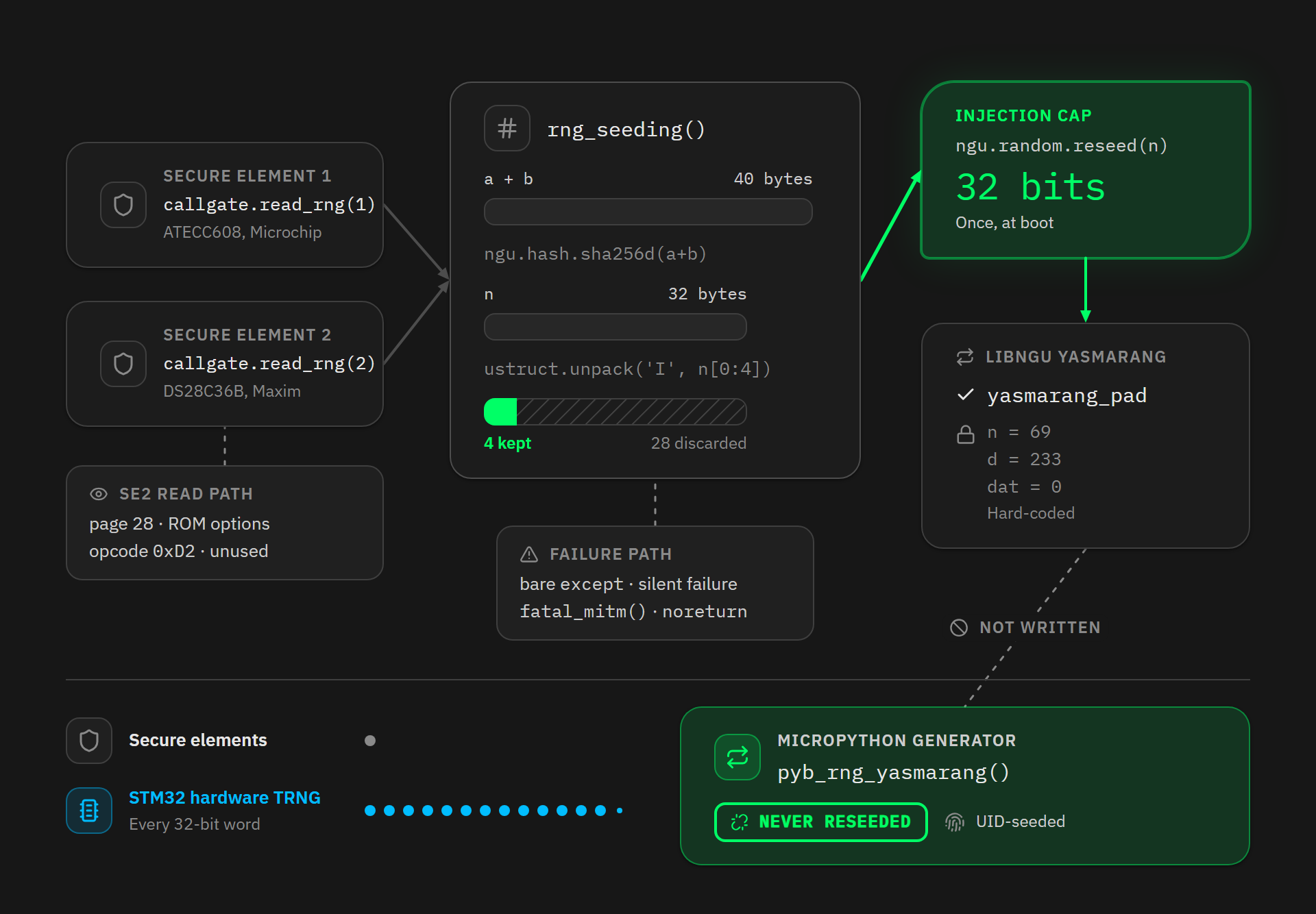
The device queries its 2 secure elements at boot, a Microchip ATECC608 and a Maxim DS28C36B, hashes their outputs, and injects the result back in. For SE1 this really is hardware randomness, and it sets these models apart from the Mk3. For SE2, we will see below that the code does not issue the part’s random command, so the value read cannot be quantified.
4 caveats apply here.
First, ustruct.unpack('I', n[0:4]) keeps only 4 bytes: the function receives 40 bytes, computes a 32-byte digest, and throws 28 away. The injection is therefore capped at 32 bits. Capped, not equal to, because the code produces a 32-bit value without guaranteeing it carries 32 bits of entropy.
Second, on the C side, the reseed overwrites only one state variable out of 4:
STATIC mp_obj_t random_reseed(mp_obj_t arg)
{
    yasmarang_pad = mp_obj_get_int_truncated(arg);
    return mp_const_none;
}
ngu/random.c:162-167 - switck/libngu @ 537519a8
n = 69, d = 233 and dat = 0 keep their hard-coded values. And above all, MicroPython’s generator, the one seeded by the identifier, is never reseeded at all. That is why the unique identifier still matters even on recent models.
Third caveat, this call runs inside a try block with a bare except clause, in shared/main.py:53-64. There is a path on which the reseed fails silently, leaving the generator on its public constants. But rng_seeding() is the last statement in init0(), and it is the call to mk4.init0() that this try covers, swallowing every exception crossing init0() without being caught locally. Inside that function, mounting the PSRAM does have its own try, which isolates its failure. Creating the flash filesystem runs inside the error handler of os.statvfs() with no protection of its own. A failure there travels up to the bare except and skips the reseed without anything appearing on screen.
A genuine secure-element failure, on the other hand, does not take that path. In the bootloader, se2_read_rng() opens on if(setjmp(error_env)) fatal_mitm();, and on the SE1 side, ae_secure_random() calls fatal_mitm() as soon as the authentication digest fails to match. That function is declared noreturn: it shows the alert screen, wipes SRAM on production builds, and locks the device. No exception travels up to Python, so the silent failure is real but conditional.
Fourth caveat, the SE2 path does not call the part’s random command. The DS28C36B does have one, opcode 0xD2, and Coinkite knows it: its own driver, since filed away in misc/obsolete-code/ds28c36b.py, implements it and marks it “do not use for any purpose”. The reason is that its output travels in the clear over the I2C bus, where an interceptor can substitute it in flight. Instead, se2_read_rng() performs an authenticated read of page 28, the “ROM options” page, and returns bytes 4 to 11 of it. This detour is still fed by the chip, since Maxim application note AN6435 states that the contents of pages 28 and 29 “can change on each read with the inclusion of a random page seed”, which is precisely what the code comment calls the “RPS” bytes.
Be careful what you conclude from that, though. The code proves that a variable, authenticated value is read at every boot, but not how many bits of entropy it carries, since it does not come from the part’s random command but from a side field of an options page. Since the full DS28C36 datasheet is not public, nobody outside Maxim and Coinkite can settle it.
The upshot: both secure elements are indeed queried, but only once, at boot, and everything they contribute ends up crushed into 32 bits. The microcontroller’s generator, meanwhile, was supposed to be queried for every word produced, for the whole life of the device. That is the one that was never reached.
9 - What is broken and what is not
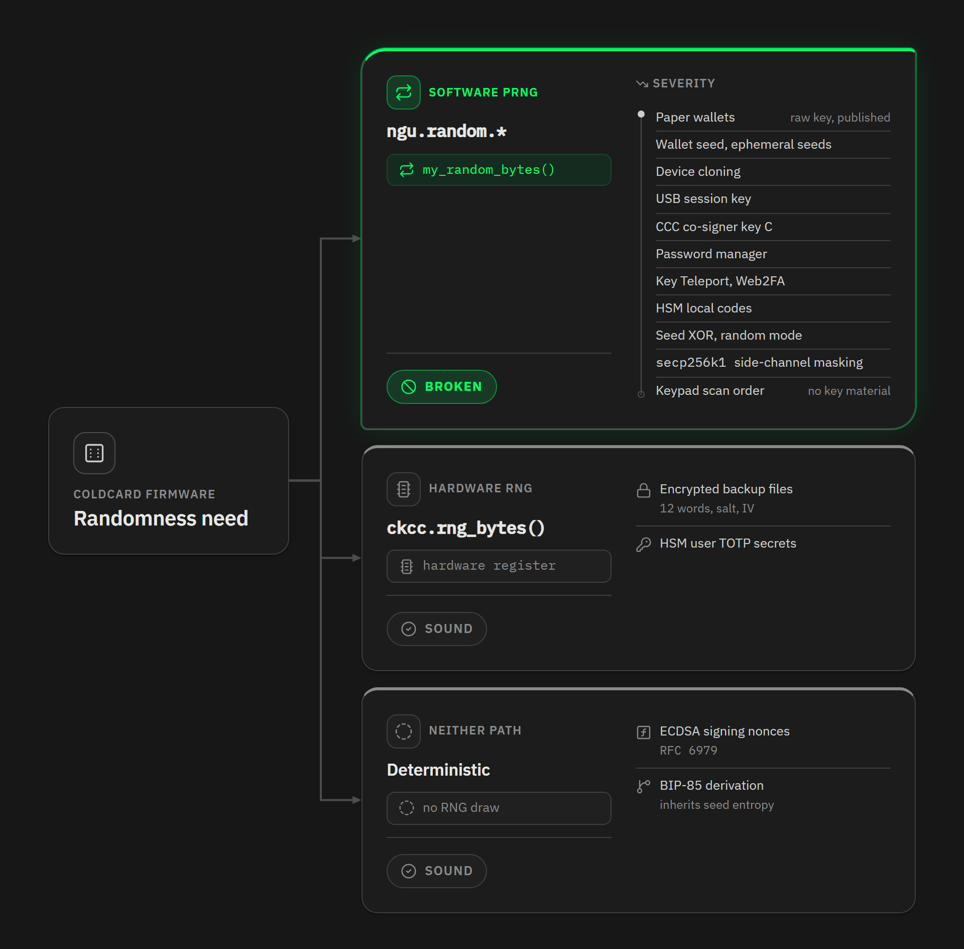
We have measured what this randomness was worth. That leaves where it flowed. There are 2 distinct routes to randomness in the firmware: the one through ngu.random.* was broken, and the one through ckcc.rng_bytes(), which reaches the hardware register directly, always worked correctly.
| Function | Route | State |
|---|---|---|
| Wallet seed, ephemeral seeds | ngu.random |
Broken |
| Paper wallets | ngu.random |
Broken, the private key is the generator’s raw output |
| Cloning to another device | ngu.random |
Broken |
| Encrypted USB session key | ngu.random |
Broken |
| Co-signer key C | ngu.random |
Broken |
| Password generator | ngu.random |
Broken |
| Key Teleport, Web2FA | ngu.random |
Broken |
| HSM local approval codes | ngu.random |
Broken |
| Seed XOR in random mode | ngu.random |
Broken |
| secp256k1 side-channel masking | ngu.random |
Broken |
| Keypad scan order | ngu.random |
Broken |
| ECDSA signing nonces | RFC 6979 | Sound |
| Encrypted backup files | ckcc.rng_bytes |
Sound |
| HSM user TOTP secrets | ckcc.rng_bytes |
Sound |
| BIP-85 derivation | derived from the seed | Sound, but inherits the seed’s quality entirely |
3 points deserve a closer look.
The most important one is signing nonces, because if the ECDSA nonces had come from the broken generator, the private key would have leaked on every signature, even for a perfectly sound seed. The answer is reassuring: libngu/ngu/k1.c:336 calls secp256k1_ecdsa_sign_recoverable with secp256k1_nonce_function_default, that is the deterministic generation of RFC 6979, and the extra parameter is only a grinding counter used to obtain short signatures, itself deterministic. In practice, a seed imported from another device or built with dice leaked nothing through its signatures, even after thousands of them on vulnerable firmware.
Encrypted backup files are sound: their 12 protection words come from ckcc.rng_bytes, as do the salt and the initialisation vector. Cloning to another device is broken, even though it lives in the same file and produces the same archive format. For a backup, the encryption key is the 12-word password drawn from hardware. For a clone, the 2 devices exchange an ephemeral key over the SD card, and that key comes out of ngu.secp256k1.keypair(), so out of the broken generator. The same call feeds the ephemeral pair of the encrypted USB session, at usb.py:715, and ngu.random.bytes(15) supplies the HMAC key for HSM local approval codes, at hsm.py:857. Be careful, though: saying the backup is sound does not mean its contents are. If the seed it holds was built on a vulnerable device, it stays vulnerable once restored.
The third point we flagged in a single sentence in our first analysis, without locating it in the code. The masking libngu uses as a side-channel countermeasure, ctx_randomize() at k1.c:72-79, called once before every signing session from psbt.py:2175, was fed by the broken generator too. This masking is a layer added on top of libsecp256k1, it does not replace it: the library keeps its constant-time implementations, which are its main defence. The mask still varies from one session to the next, and it comes out of the same enumerable space as everything else on this path, so it falls with that space. The keypad scan order is in the same position.
10 - What about dice rolls?
One exception remains, and it saved a lot of users: dice rolls. I verified it on Coinkite’s desktop simulator, which runs the firmware’s own Python code on a PC. Instrumenting the fixed build function by function, I recorded every call and every write to the accumulator.
On this path, the SHA-256 accumulator starts on an empty string, at seed.py:476, and takes only the rolls. The keypad draws from the generator on every burst, as section 7 describes, and those bytes go to the scan order. The seed is exactly BIP39(sha256(string of rolls)). On a trace of 100 rolls, the opening digest is e3b0c44298fc1c149afbf4c8996fb92427ae41e4649b934ca495991b7852b855, the canonical hash of the empty string, so the accumulator holds nothing before the first roll.
2 caveats though, for anyone using the mixed mode. The distribution check that rejects a set of rolls where one face exceeds 30% sits at seed.py:452, but it is only active if the judge_them parameter is true. And the mixed mode reachable with key 4 from the words screen calls add_dice_rolls(0, seed, False), which disables both that check and the minimum roll count. Coinkite’s advisory sets the thresholds out plainly, incidentally: from 50 to 98 private, fair and independent rolls, the seed holds at least 128 bits; from 99 onwards it holds about 256; and below 50, or if the count is unknown, you have to migrate.
11 - 5 safeguards, 5 failures
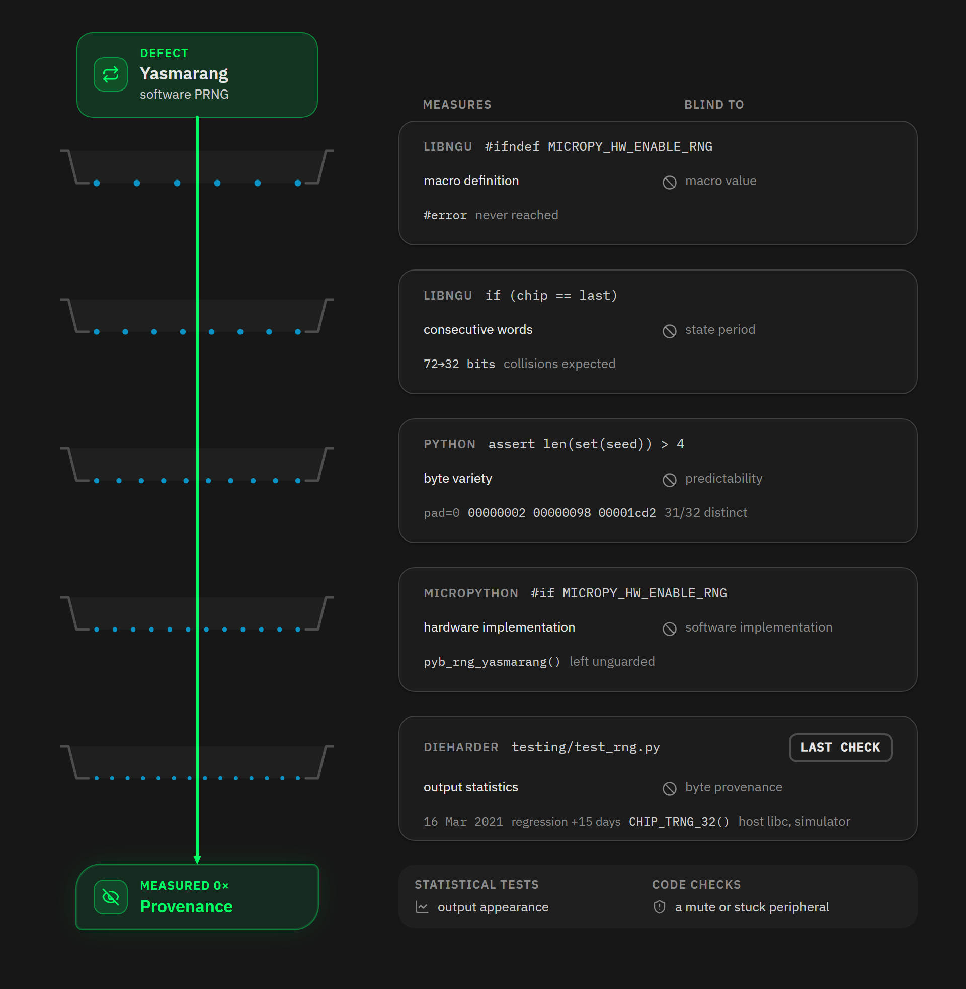
What stands out on rereading this code is not the absence of protections. It is that there were 5 of them, and that none of them worked.
libngu’s build-time guard tested whether the macro was defined instead of what it was set to, and could not fire on this platform.
The if (chip == last) test in my_random_bytes was meant to catch an unclocked generator, but it compares 2 consecutive output words and nothing more. It does not test the period of the transition function, since 2 different internal states can produce the same output word, Yasmarang’s output function compressing 72 bits of state into 32. What it catches is a peripheral always returning the same value, and a first draw of zero, since last is initialised to zero. A software generator advancing normally passes it trivially.
The assert len(set(seed)) > 4 assertion measures how many distinct values appear in 32 bytes. For uniform bytes you expect around thirty distinct ones, and dropping to 4 or fewer has a probability on the order of 2^-165. This assertion never measures predictability, only variety.
MicroPython’s #if MICROPY_HW_ENABLE_RNG block did exactly what it said, but it guarded the hardware implementation, not the software one.
Finally a statistical test existed. testing/test_rng.py was added on 16 March 2021, 15 days after the regression went in, and it runs Dieharder on ngu.random.bytes(). Without --dev it draws from the simulator, where CHIP_TRNG_32() is wired to the host’s libc, so the bytes under test never come from MicroPython’s copy.
12 - What the fix actually changes
The fix of 31 July 2026 is worth examining, because it is not where you would expect it. Neither libngu nor MicroPython is modified, and the submodule pointers are identical before and after. MICROPY_HW_ENABLE_RNG stays at 0, and this commit leaves the faulty #ifndef guard untouched.
The workaround happens entirely at build time. In commit ca724637, the board exports its own global symbol:
uint32_t rng_get(void)
{
    return rng_get_or_fault();
}
stm32/COLDCARD/rng.c:82 - Coldcard/firmware @ ca724637
MicroPython’s object file is neutralised by compiling it from /dev/null, and a verification target runs arm-none-eabi-nm over the resulting objects to fail the build if the upstream symbol reappears.
That is a build-time guarantee, not a runtime one. stm32/COLDCARD/rng.c enforces a 10 millisecond ceiling on the arrival of a word from the hardware generator, and raises an error beyond it. In the same file, random_buffer() refuses 2 identical consecutive words, as does my_random_bytes() in libngu. These detect hard failure, a peripheral gone silent or stuck on one value. None of them tests where the bytes come from, which is what failed here.
Runtime checks came later, in 2 commits. On 1 August, commit 82ced47a reads RNG_SR_SEIS and RNG_SR_SECS, rejects a zero word, retries at most 3 times and raises MP_EFAULT once all 3 fail. On 4 August, 43b21392 discards 12 words after clearing SEIS, per RM0432 section 32.3.7. Both sit inside rng_get_or_fault(), the function the linker was bypassing, so they harden the hardware path without testing whether that path is the one taken. 43b21392 touches those 2 files only. 82ced47a touches 5, adding the changelog plus shared/keyboard.py and shared/mempad.py. There, shuffle(self.scan_order) moves inside a try/except OSError, so an RNG fault can no longer leave the keypad dead before login.
Those 2 commits sit on master, so they cover the Mk4, Mk5 and Q. The Mk3 builds from v4-legacy, where the same hardening landed on 12 August 2026. a60f7686 brings the SEIS and SECS handling to stm32/COLDCARD/rng.c and to the bootloader, and 099b72f5 adds a self-test that runs at boot, counts the words rng_get() pulls through the hardware read path, and bricks the device if the count comes out wrong. That self-test is the one check in this whole story that looks at the path rather than at the output. The Mk4 got its own the next day, with 7ac5d98a on 13 August. Neither has shipped yet: on the Mk3 side the changelog files it under 4.2.1, still marked TBD.
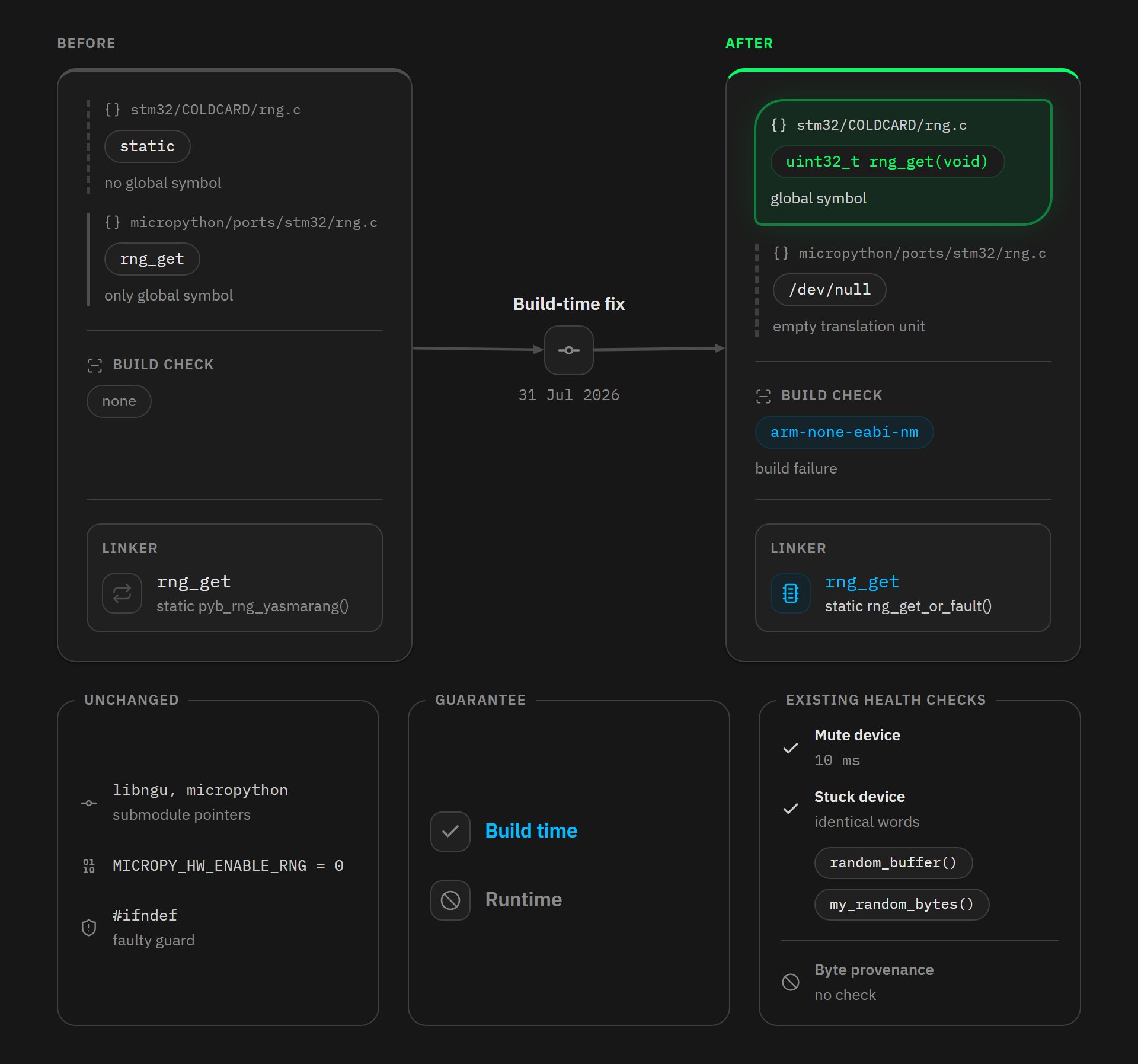
13 - What a sweep would cost
Testing one candidate runs a chain: PBKDF2-HMAC-SHA512 and its 2,048 iterations to stretch the mnemonic into a seed, the BIP32 derivations, an elliptic curve multiplication per address, then a lookup in the set of funded addresses. PBKDF2 dominates that chain. The curve multiplication is worth a few percent of the cost of one candidate, and the lookup runs in constant time with a Bloom filter.
Taking about 1.5 million candidates per second on an RTX 4090, an order of magnitude taken from the literature, and 0.30 dollars per hour of rented GPU:
| Space | A single RTX 4090 | Rental cost |
|---|---|---|
| 2^22, an Mk3 whose draw rank is known | 3 seconds | negligible |
| 2^28 | 3 minutes | 0.01 dollars |
| 2^32.05, the same Mk3, rank assumed between 0 and 1,000 | 50 minutes | 0.25 dollars |
| 2^40 | 8.5 days | 61 dollars |
| 2^46, an Mk4 whose full identifier is known | 1.5 years | 3,900 dollars |
| 2^52, the modelled slice of an Mk4 | 95 years | 250,000 dollars |
| 2^60 | 24,400 years | 64 million dollars |
2 rows need explaining. The Mk3 one at 2^32 adds the 1,001 draw ranks of a chosen range from 0 to 1,000 on top of the 4,456,448 starting states, since there is no way of knowing how many keys the owner pressed before creating the seed. That makes 2^32.05 candidates in total, and 50 minutes instead of 3 seconds. This is not an exhaustive sweep, since the firmware puts no cap on that count. The Mk4 one at 2^46 assumes the identifier is known exactly, which the serial number does not give, as we saw in 5.3: with the serial number alone, you come down to 2^51.2 at the median, barely below the 2^52 row.
These times are extrapolations under the assumption of 1.5 million complete candidates per second, BIP32 derivations and address lookup included, which I have not measured end to end. They also assume the passphrase is known, in practice the empty one: a strong, unknown passphrase adds its own search space on top of this whole table. And on recent models, the 2^52 row prices the modelled slice, RTC and draw rank excluded, not a complete attack.
This table prices the mnemonic path, the one where PBKDF2 is the bottleneck, and the other rows of section 9 do not go through it. For example, a paper wallet key is the generator’s raw output, so testing one candidate costs a curve multiplication and a hash instead of 2,048 PBKDF2 iterations.
What these times show is a difference in kind and not merely in degree between the Mk2/Mk3 and the Mk4, Mk5 and Q: 3 seconds of compute on one side, about 74 years on the other. The gap between the 2 modelled slices is worth 29.5 bits, and it comes entirely from the secure-element reseed: its 32 bits, minus the 2.5 bits pad loses along the way on these models. It is the only mechanism in this chain that genuinely worked.
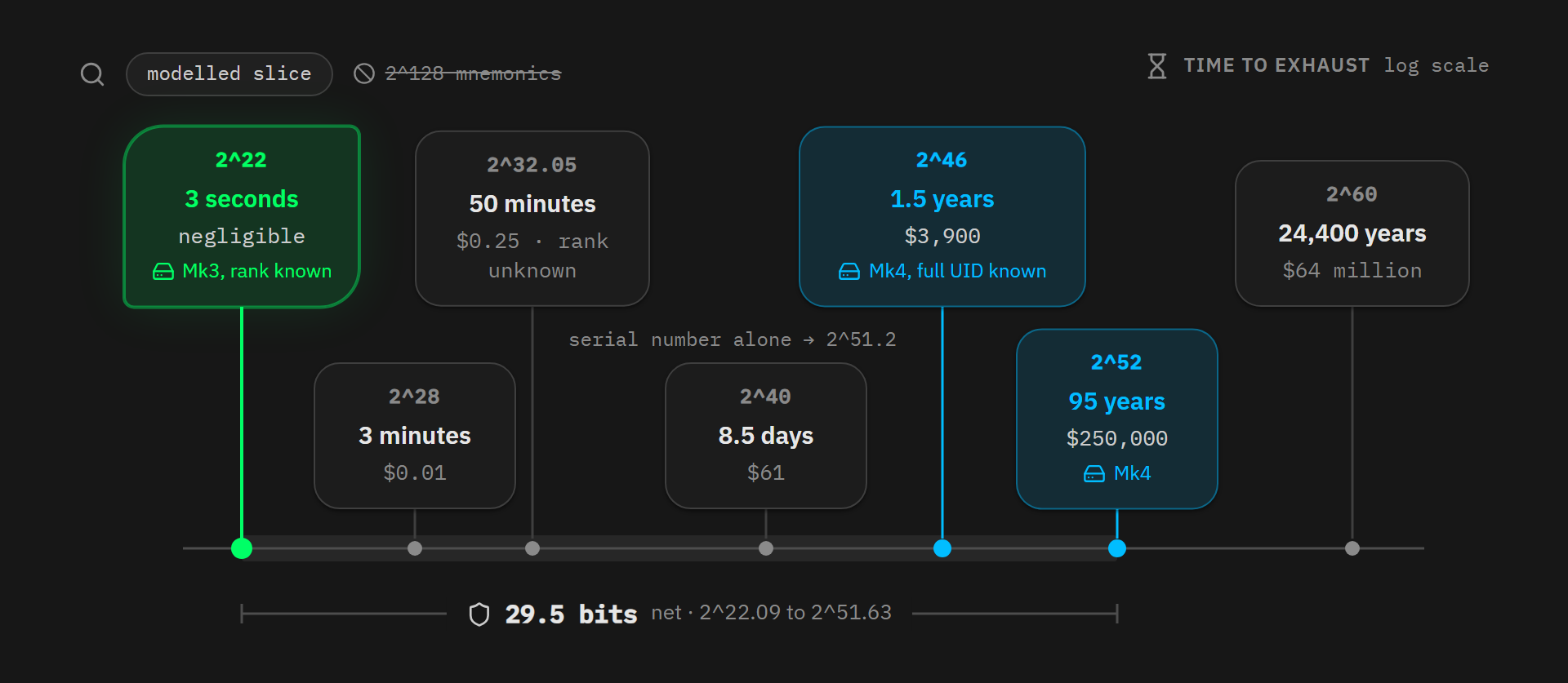
This table also explains why BIP39 stretching does not save the day. Its 2,048 iterations do their job, and they are where the times in the table above go, but a multiplicative cost per candidate does not make up for the loss of several dozen bits of entropy. The attack does not walk through 2^128 mnemonics, it walks through the generator’s state space, and at that scale PBKDF2 only turns seconds into minutes.
14 - The limits of this analysis
For the sake of honesty, here is what cannot be verified or remains approximate.
The entropy estimate for the identifier is a derivation, not a measurement. The 3 sets of real coordinates I have are from a forum post and a GitHub issue, and the 3 mm edge margin is a convention of mine. The reliability report that gives the wafer diameter and the scribe line covers the STM32L4 family without naming the Coldcards’ L496 and L4S5. The sign-magnitude format is documented for the STM32C0, not for the L4, and the sample I decode is an L476 rather than one of the Coldcards’ 2 parts. ST itself admits the coding can vary from one factory to another. That rules out treating the number of positions on a wafer as the number of possible values across all production. The robustness sweep limits how far these weaknesses reach, since the result stays between 10.8 and 12.6 bits across the whole plausible range, but nobody has yet read the coordinates off a batch of real Coldcards to settle it.
The RTC registers’ contribution on the Mk4, Mk5 and Q is not measured: the reasoning establishes that they are not worth the 24.4 bits advertised, but not what they are actually worth. The computation also assumes SysTick->VAL is uniformly distributed at seeding time, which is already doubtful for a human finger. On the Mk2 and Mk3, where the RTC is worth zero, the space figures given here are therefore upper bounds. On recent models they are not: the 2^52 leaves out the RTC and the draw rank, which enlarge it, and it credits the reseed with its full 32 bits, which are only a ceiling. It is a conditional slice, neither an upper nor a lower bound.
The size of the Mk3 fleet is unknown. The 30,000 units carried from 6.2 onwards is a working assumption and not a measurement. Coinkite has never published its volumes and it ships no GitHub release whose download counts could stand in for them. Taken one by one the 3 routes behind that figure are all weak, and together the tightest bracket they give is thousands to tens of thousands. Anything computed from the fleet moves with its square, since collisions are counted over pairs, and a fleet of N gives about N^2/2 of them. Divide the fleet by 3 and the 120 pairs sharing a starting state fall by a factor of 9. Triple it and they climb by the same factor. The 68-device threshold is the one figure that does not move, because it never depended on the fleet at all.
The position counts on the wafer and the enumerations of the pad space are reproducible from the dimensions and ranges cited. The dice path trace, on the other hand, was taken on the simulator, and the throughput of 1.5 million candidates per second on an RTX 4090 is an order of magnitude taken from the literature, not a measurement made end to end.
15 - What this incident says about engineering generators
I want to close on what strikes me as transferable, beyond this one manufacturer.
The first lesson is about the nature of testing. A statistical battery applied to a single output stream could not detect this failure, because a pseudo-random generator is designed precisely to pass it: these tests measure how the output looks, never how unpredictable it is. The checks present in the code could do no better, because they look for a peripheral that has gone silent or is stuck, not for a peripheral that is never queried. Comparing 2 devices, or one device across reboots, would not have caught it either. The broken generator takes its seed from the identifier and the SysTick, so its stream already differs from one unit and one boot to the next, exactly as a working generator’s would. What discriminates is the path, not the output: which rng_get the seed code binds to in the link map, whether RNG_DR is ever read, whether a seed still comes out with the hardware generator switched off. The firmware tested none of that.
The second lesson is about what a code review actually verifies. Coinkite puts it with an honesty that deserves credit:
Existing review confirmed that the intended TRNG implementation was present in the firmware binary, but did not verify which rng_get() implementation the wallet seed-generation path actually reached across the two submodules.
Verifying that a symbol is present in the binary is not verifying that it is reached. The whole flaw sits in that gap, and it runs across a submodule boundary, which is precisely where reviewers stop looking.
The third lesson concerns specifications. The intent was public and written down: shared/seed.py:603 opens generate_seed() on “Generate 32 bytes of best-quality high entropy TRNG bytes”. The Python line under that comment is faithful to it. The contradiction appears a layer down, in the symbol the linker binds, and no public document from the time says which symbol that call has to reach across which submodule boundary. That missing piece is what the nm check added in July now enforces.
The fourth lesson, finally, is the one we keep repeating and that this incident illustrates: a single entropy source is a single point of failure. The architectures that held up are the ones that funnel several independent sources into one digest, so that a failing source cannot bring the result down. This is the principle of dissimilar redundancy, and it applies inside a device just as much as it does across the devices of a multi-vendor multisig setup.
Sources
- The code, which is the primary source for everything above: Coldcard/firmware (commit
bcc2c382for the pre-fix state,ca724637for the fix itself,82ced47aand43b21392for what followed, branchv4-legacyfor the Mk2 and Mk3), switck/libngu at commit537519a8, whichmasterpinned until 14 August 2026, and at356b9137, still pinned byv4-legacyand identical to it line for line inngu/random.c, and Coldcard/micropython at commit4107246f - Coinkite, Technical Deep Dive into the Entropy Issue and Coldcard Security Advisory
- Block Bitcoin Engineering and Security, Predictable RNG Fallback and 32-Bit Reseed in COLDCARD Firmware
- Dusty Daemon, When random.bytes() runs but doesn’t work
- Fabio Akita, Exploiting Coinkite’s RNG Egregious Problem
- Charles Guillemet, The Coldcard Incident
- Bitcoin Optech, Newsletter #416
- Coinkite, manufacturing bills of materials published in the
hardware/folder of the firmware repository, for the microcontroller part numbers fitted on each model - STMicroelectronics, datasheet STM32L496xx, DS11585, WLCSP100 and WLCSP115 sections, for the Mk3’s die size
- STMicroelectronics, datasheet STM32L4S5xx, DS12024, WLCSP144 section, for the Mk4, Mk5 and Q’s
- STMicroelectronics, RM0351 section 49.1 (unique device ID register) and section 6.4.19 (
RCC_APB1ENR1reset values by part number), RM0432 sections 58.1 and 6.4.19 for the L4+ equivalents, and RM0091 section 33.1 for the STM32F0 wording on the same register - STMicroelectronics forum, Parsing UID Fields on STM32L476 for the bit split and the real reading, and STM32C071 unique ID for the sign-magnitude coding, the announced correction to the manual, and the admission that the coding varies with the diffusion factory
- SEMI E142 and SEMI M20, for the origin convention of dicing maps (corner) and of wafer coordinate systems (centre)
- Ilya Levin, Yasmarang, the algorithm itself
- Zephyr Project, issue #37153, “USB serial number is not unique for STM32 devices”, which publishes the full identifier of 2 STM32L433 chips
- STMicroelectronics, change notifications MICROCONTROLLERS/25/14920 (2 January 2025) and MDG/19/10333, for the STM32L4 diffusion sources (TSMC Fab 14, Crolles 300), and reliability report MDG-MCD-RER1810, attached to the ASE Kaohsiung assembly notifications, for the wafer diameter and the scribe line
- PCB Artists, Generating 32-bit STM32 Unique ID, 24 May 2023, for general context on this register
- Analog Devices (Maxim), application note AN6435, How to Authenticate DS28C36 Data, for the randomness field in the DS28C36’s options page
- Foundation Devices, Passport volumes announced in late 2022 and firmware download counters on GitHub
- Juan Galt, How Coinkite Defines Cypherpunk Bitcoin Security, Bitcoin Magazine, 16 April 2025, for the size of the company
- Galaxy Research, tallies of the addresses and amounts drained
- NIST, SP 800-90A and SP 800-90B
- Our first analysis: Critical Coldcard flaw: what happened, who is affected, and what to do